Hello Gents
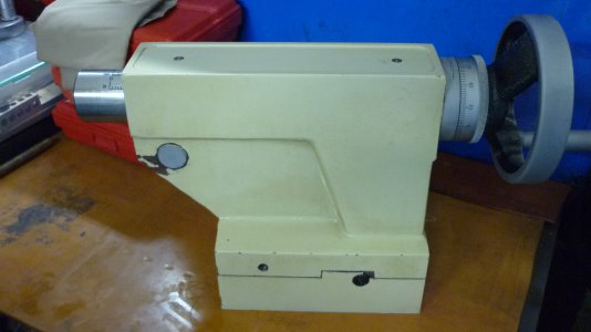
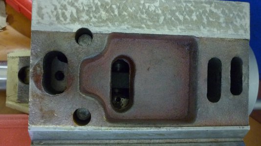
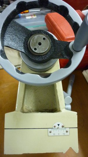
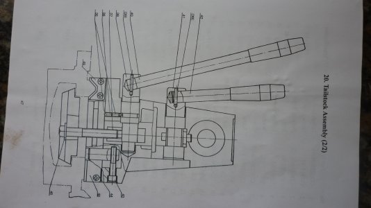
We have had a problem with our Tailstock in that the CLAMPING LEVER, (Part # 42) for the FEEDSCREW, Part # 17, ( we knew this as the Tailstock Spindle/Barrel ?), lost its springiness and would just flop back without Locking the Feedscrew.
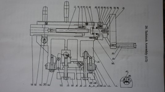
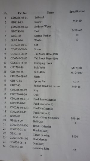
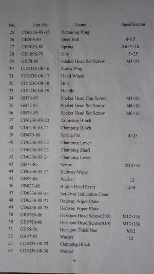
Well we thought it would be possible to dismantle the Tailstock, ascertain the problem and try and rectify this. Well obviously that was easier said than done. We would sincerely appreciate some feedback from some of U kind learned Gents on how we may dismantle the Tailstock and rectify the Clamp Lever issue. Attached are the pics from our Manual together with the specific Part Numbers which would assist our communications.
Ours is a fairly good quality Asian Metre Bed machine which we've had now for some 8-9 Years, was
new since purchase. Some of U maybe familiar with our earlier postings which greatly assisted us in understanding and operating our machine the better. We have quite some work lined up and this TAILSTOCK problem is proving a setback.
We thank U graciously in advance for taking and making time in sharing Your experience.
LORD BLESS
aRM
Front Lever (R) Flopped !!!
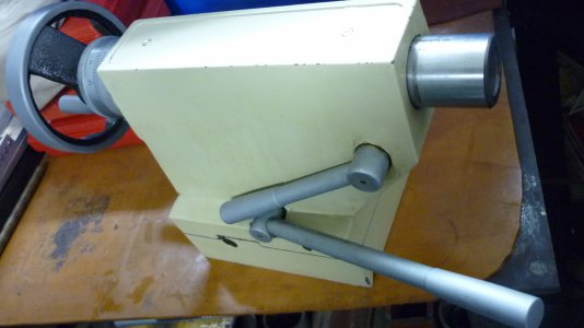
We have had a problem with our Tailstock in that the CLAMPING LEVER, (Part # 42) for the FEEDSCREW, Part # 17, ( we knew this as the Tailstock Spindle/Barrel ?), lost its springiness and would just flop back without Locking the Feedscrew.
Well we thought it would be possible to dismantle the Tailstock, ascertain the problem and try and rectify this. Well obviously that was easier said than done. We would sincerely appreciate some feedback from some of U kind learned Gents on how we may dismantle the Tailstock and rectify the Clamp Lever issue. Attached are the pics from our Manual together with the specific Part Numbers which would assist our communications.
Ours is a fairly good quality Asian Metre Bed machine which we've had now for some 8-9 Years, was
new since purchase. Some of U maybe familiar with our earlier postings which greatly assisted us in understanding and operating our machine the better. We have quite some work lined up and this TAILSTOCK problem is proving a setback.
We thank U graciously in advance for taking and making time in sharing Your experience.
LORD BLESS
aRM


Front Lever (R) Flopped !!!


