HF 7x10 Mini Lathe Compound Dial Binding

NF6X

Registered
Registered
Joined
May 18, 2020
Messages
15
I have an older Harbor Freight 7x10 mini lathe, model 33684, which I allowed to get rusty and decrepit. I'm now fixing it up and upgrading it with lots of fun stuff from Little Machine Shop: metal gears, quick change tool post, carriage lock and stop, 4" 3-jaw chuck, holder to use a Proxxon tool as a tool post grinder, etc.

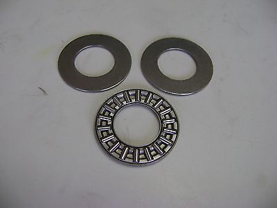
When I crank the compound slide inwards, the dial binds against the bracket supporting the lead screw, and it holds still while the screw turns. Looking at how it's designed, I don't see how it could do anything else except by dumb luck. It sure looks to me like the dial serves as one of the thrust bearing surfaces when cranking inwards, with the little spring, crank-to-dial friction, and dial-to-bracket friction all competing over who gets to turn the dial. My cross slide's dial does not seem to be binding like that at the moment.

Am I missing something here, either physically or conceptually? I can imagine that adding a radial thumb screw in the dial to clamp it to the lead screw might make it slightly less awful, but it sure seems to me like the dial shouldn't be playing any role in bearing the feed screw thrust load. I wonder if anybody has re-designed the feed screw thrust bearing scheme to work better.
 
I drilled and tapped the dial for a set screw that I use to tension the curved flat spring in the dial. Adjusted until the dial only spins on the lead screw when I want to zero it. I installed a needle thrust bearing with its 2 hardened washers in the bracket and made the depth of the bore in the bracket deep enough to keep the dial and bracket about .002" apart so they never touch each other touch each other. I think the needle bearing is this check the measurements on your lead screw and bracket to make sure:
It is a poor design from the factory.

Roy
 
Last edited:
Here are the LMS instructions for mounting the lead screw and pillow blocks on the 16" extended bed. They may help you getting this all adjusted.

Roy
 

Attachments

  • Position Lead Screw and pillow blocks and adjust.pdf
    78.8 KB · Views: 244
Adding a needle thrust bearing sounds like a nice improvement. What keeps the flat spring in place under the set screw when you turn the dial to re-zero it? I'd think that the flat spring would be more inclined to stay put with respect to the lead screw rather than staying put with respect to the dial.
 
That spring is stuck between two washers in its bore so it can't move out of place. You can order another spring from LMS and put them in forming a complete circle so they will always have the extra tension on them. That's how I did it.

Roy
 
I'll try bumping around the pillow blocks to see if I can get them aligned better. I can't help but wonder whether I might be able to do better than plain iron bearings with no oil holes for the lead screw. If I understand correctly:
  • The lead screw axis needs to be aligned well with the path that the centroid of the half nuts follows.
  • Axial free play on the lead screw should be minimal, and the machining forces will turn into thrust on the lead screw against one pillow block or the other depending on direction of carriage travel.
  • There isn't much radial load to deal with in the pillow blocks.
  • Radial free play on the left side should be minimal, both to position the lead screw with respect to the half nuts in the apron and to keep the drive gears meshed nicely.
  • Radial free play on the right side is less critical because it's just keeping the lead screw from flapping in the breeze too much.
Thus, it seems to me that I might safely increase radial bearing clearance a tiny bit on the right pillow block if I can't eliminate the binding by bumping around the pillow blocks, but I probably want to leave the left block's radial bearing alone and I don't want much axial free play at all. Does that make sense?
 
I also bored out the other side of the compound bracket for I think 1mm ball bearings and used 24 or 25 bearings. They ride against the flange on the lead screw and the bore I made 1mm deep so the bearings are captured. I lubed them with 65% moly containing grease. The compound is smooth as silk in both directions now. This was done in 2017 and it is still going strong. I ordered spare parts from LMS first in case I screwed up, but I accidentally got it right on the first try. It is so smooth it is scary.

Also one of the most useful upgrades is the LMS extended cross slide kit. Probably the best mod I've made besides the 16" bed and tapered roller bearings on the spindle. I also made tapered gibs for the carriage and that is a tie for the best upgrade. Got to love LMS, they have everything a minilathe could ever want.

Roy
 
When I added the extended bed I also drilled the pillow blocks for oil fittings:
I slid a piece of windshield wiper hose (1/8" or 3/16") over the end of my oil pump can to lube the pillow blocks. The rubber hose extends about 1/6" from the end of the oil can spout so it is compressed when I push the spout down onto the oiler. This lets me give a good shot of oil to the lead screw without making a mess.

Roy
 
My pillow blocks don't have oilers, or even plain holes. Just the ability to hose against the exposed right end of the shaft. I ought to at least drill a hole in the top of each one to drip in some oil.

Derp. I missed where you wrote that you drilled them for oilers.
 
Last edited:
Back
Top