Hitachi vfd help, phoenix az

If you are turning to a shoulder or threading to a particular point you want the lathe to stop at that position. If you are threading and then need to reverse the cutter, you back out the cutter, press the bypass button and reverse the carriage. I thread at 250-600 RPM, often to a shoulder, there is no way to do this repetitively and have the cutter stop repeatably within 0.001". When doing any thype of threading I do not disengage the half-nut until I am done threading, which usually can be completed in under a minute. Also for blind boring and turning to a shoulder. It is also a safety feature when turning close to the chuck, then getting distracted and crashing your lathe. If you do not want to use it, you can add a jumper at the control panel and remove the P-sensor.
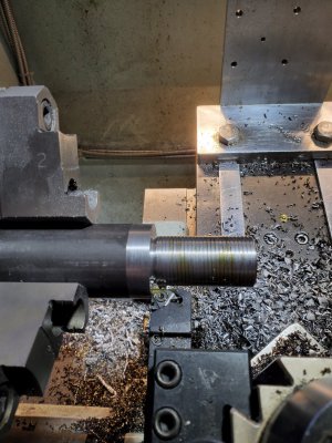
20230113_142700.jpg

Threading 1144 steel rod 1-14 at 300 RPM to a shoulder, 9 passes to a depth of 0.098".
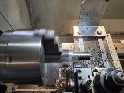
20230113_142926.jpg
 
I figured threading would probably be the most practical use for something like this. I can see where you would want a safety while cutting threads at higher speeds. Doing internal boaring I usually use the manual carrage stop as a starting point and work my way out with the power feed or I go into the hole by hand not using the power feed. And to the point on working close to the chuck I can see some benefits to having a safety there. I plan on leaving it for now and will probably ad an additional switch to this circuit on the foot brake. As of right now unless there is a feature on the vfd that shuts power down to the motor if a specified load is exceded there is no safety on the foot brake to power down the spindle when you step down...

Thank you for the input.
Mike.
 
Then it is probably not one of my control systems, as all of lathe control systems I build have an interlock system connected to the foot brake which both shuts down the power relay and issues a free run command to the VFD so it does not fight the VFD braking. If the brake is released the lathe cannot restart, it must always be in the stop mode to reset the control system power relay. I also use an additional mechanical limit switch in addition to the proximity sensor as a redundancy backup should the proximity sensor fail. The problem often is people do not use the proximity sensor in this application as a complete control system, and that can pose additional safety risks in my opinion. I would post some pictures of the control cabinet and the front panel/proximity sensor system and I can give you some additional guidance. Please indicate the lathe model.
 
Well as of right now I have the lathe working, I do not know yet what the additional switches do as of yet. I have been trying to get a full wiring diagram drawn up of the machine however there are a few extra components in the factory electronics box on the back side of the spindle head that I don't have easy access to as of this moment. It will have to wait until I move the lathe again before I can get into there and get a good reading on what goes where and draw out a proper diagram. I will see if I can get some pictures uploaded of what all is in there when I have time this weekend, I have been busy working on getting my PM-833TV set up and ready for the CNC conversion.
 
Hi @mike96

Well as of right now I have the lathe working, I do not know yet what the additional switches do as of yet. I have been trying to get a full wiring diagram drawn up of the machine however there are a few extra components in the factory electronics box on the back side of the spindle head that I don't have easy access to as of this moment.

I did my own VFD conversion to my PM1440GT using solid state circuits rather than the mechanical relays. Doing so allowed me to fit all of the components in side the lathe stand where the original electroncs were placed. I posted the detailed description of it and in the attached documentation and photos. I even described features of the VFD. Yes, mine has a proximity sensor etc as well. Even if the previous owner followed Mark's build you may find my write ups useful to understanding the operation. There are two documents, Part 1 and Part 2, plus photos at the link below. You will want Part 2. Part 1 describes the original factory wiring prior to the VFD conversion. There will be more information than you will need, but scan through Part 2 and you will find a portion about the VFD operation.

VFD conversion using solid state electronic components.

Good luck,

Dave L.
 
Back
Top