Hitachi VFD Torque Settings

TomS

Active User
H-M Supporter Gold Member
Joined
May 20, 2013
Messages
1,906
I have a PM-932 converted to CNC with the spindle driven by a 2HP 3Ph Marathon Black Max motor and a Hitachi WJ200 VFD. My question is are my VFD settings correct for constant torque at low rpm? I'm asking because I was milling 6061 with a new 2 flute 1/2" carbide end mill at 5000 rpm, .100" DOC, .438 WOC, and the motor bogged down and snapped the end mill. I thought my settings were relatively conservative. My thinking is I've overlooked a VFD parameter setting somewhere. Any help given is appreciated.

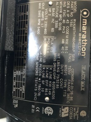
My pulley ratio is 2.5:1 which gives me a rpm range from 345 to 1380 in the low range and 2156 to 8625 in high. I've attached a photo of my motor data plate for info. If you need more info let me know and I will dig it up and post it.

Here are my current settings for the torque related parameters -

A041 - Torque Boost Select
01:(Automatic torque boost)

A042 - Manual Torque Boost Value
1%

A043 - Manual Torque Boost Frequency
5%

A044 - V/f characteristic curve
03:(Sensorless vector (SLV))

B040 -
Torque limit selection
00:(Quadrant-specific setting mode)

B041 -
Torque limit 1 (fwd/power)
200%

B042 -
Torque limit 2 (rev/regen.)
200%

B043 -
Torque limit 3 (rev/power)
200%

B044 -
Torque limit 4 (fwd/regen.)
200%

B045 -
Torque LAD STOP selection
00:(Disable)

C054 -
Over-torque/under-torque selection
00:(Over-torque)

C055 - Over/under-torque level(Forward powering mode)
100%

C056 - Over/under-torque level(Reverse regen. mode)
100%

C057 - Over/under-torque level(Reverse powering mode)
100%

C058 - Over/under-torque level(Forward regen. mode)
100%

C059 - Signal output mode of Over/under-torque
01:(During constant speed only)

IMG_0571.JPG
 
The settings seem reasonable, they are what I typically use. B022 should probably be set to 150%, but you could try 180%, this is the overload limit for up to 1 minute so if you are doing constant milling I would be more conservative as this is only short term overload. Looks like you are operating the VFD from 30-120 Hz which is a good speed range for this motor. When running the motor above 60Hz torque will fall off in a somewhat non-linear fashion and above 90 Hz you are probably 50% down. Running sensorless vector and with this motor your torque will be essentially flat from 60 Hz down to a Hz. Ideal setup for the range of RPM would be a 3 Hp motor, but size and weight become an issue.

If the end mill snapped was there an issue of coolant/loading up on the endmill. They can often gum up with aluminum and they can snap when power feeding. Also the type of end mill can be a factor, I typically use a 3 flute high helix end mill for aluminum, worked much better than 2 flute with less chatter. I use air with light application of cutting fluid. Have no experience with CNC so do not know what would be reasonable rates of metal removal/parameters.
 
My pulley ratio is 2.5:1

That might be a bit much. Your Black Max motor is rated at 5400 RPM, so I would use the motor speed. On my mill I have a 3HP motor with a 1.5:1 ratio, and I run out of torque when tapping 1/2-13 in steel in high speed.

A 1.5:1 ratio would give you 8100 RPM, with 50% more torque at the spindle.

I don't know the Hitachi VFDs well, but I assume you have SLV turned on and ran the auto tune routine.

As far as bogging down and breaking the end mill, could be a lot of things, but that normally happens when there is not enough coolant for the endmill to stay lubricated in a heavy cut. Or some times the chip load is just too high. Your width of cut might also be a bit high, about 40% is more forgiving.
 
The settings seem reasonable, they are what I typically use. B022 should probably be set to 150%, but you could try 180%, this is the overload limit for up to 1 minute so if you are doing constant milling I would be more conservative as this is only short term overload. Looks like you are operating the VFD from 30-120 Hz which is a good speed range for this motor. When running the motor above 60Hz torque will fall off in a somewhat non-linear fashion and above 90 Hz you are probably 50% down. Running sensorless vector and with this motor your torque will be essentially flat from 60 Hz down to a Hz. Ideal setup for the range of RPM would be a 3 Hp motor, but size and weight become an issue.

If the end mill snapped was there an issue of coolant/loading up on the endmill. They can often gum up with aluminum and they can snap when power feeding. Also the type of end mill can be a factor, I typically use a 3 flute high helix end mill for aluminum, worked much better than 2 flute with less chatter. I use air with light application of cutting fluid. Have no experience with CNC so do not know what would be reasonable rates of metal removal/parameters.

Glad you chimed in. The settings I posted came from a parameter doc you sent me when I did my belt drive conversion. I'll play with the B022 setting as you suggested. Running at 5000 rpm is about 65 to 70 hz. I would think the motor torque would be sufficient to run a 1/2" end mill with the DOC and WOC I programmed in aluminum. I'm running flood coolant so that was not a factor.
 
That might be a bit much. Your Black Max motor is rated at 5400 RPM, so I would use the motor speed. On my mill I have a 3HP motor with a 1.5:1 ratio, and I run out of torque when tapping 1/2-13 in steel in high speed.

A 1.5:1 ratio would give you 8100 RPM, with 50% more torque at the spindle.

I don't know the Hitachi VFDs well, but I assume you have SLV turned on and ran the auto tune routine.

As far as bogging down and breaking the end mill, could be a lot of things, but that normally happens when there is not enough coolant for the endmill to stay lubricated in a heavy cut. Or some times the chip load is just too high. Your width of cut might also be a bit high, about 40% is more forgiving.

Jim - thanks for responding. Yes, SLV was turned on and I ran the auto tune routine. I run flood coolant through two nozzles so there was more than enough coolant at the cutter/material interface. At 5000 rpm the motor is running at about 65 to 70 hz. I would have thought there was sufficient torque for the programmed DOC and WOC. For info the CLPT is .0025".

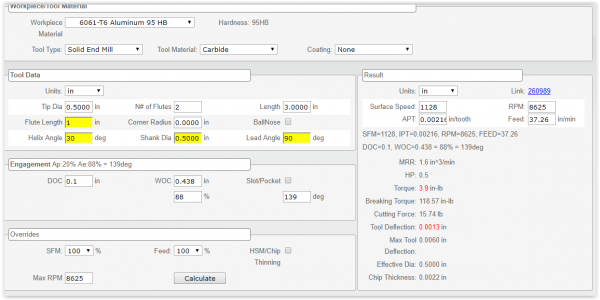
Here's a screen shot of the speed and feed calculator I use. All indications are it "should" have worked. Obviously it didn't work so I learned that the info spit out by the calculator isn't gospel.

Screen Shot 12-30-18 at 05.10 PM.PNG
 
Agree, your motor is working at a sweet spot performance wise, the question was it bogging down during the cute or acutely which would determine if it was maxing out on power vs. an acute event. It would be helpful to know the motor amperage to see if the motor is maxing out current wise. See display parameter d002, you could probably output the current load to a % meter so you could see what is happening load wise dynamically as you mill. I would need to look into the details if it is something you would be interested in. There are also factors, as some calculators are based on more rigid larger CNC mills.

The calculations look reasonable, although somewhare I saw a 25% reduction if the DOC was 2x the diameter of the endmill, but I figure this would be built into your calculator. Since I usually mill at about 50-75% of what the calculators come up with, and this is manually, I would defer to others with more experience. I believe JBOLT has a similar setup to yours, you might shoot him a PM with your info and see if he has any further recommendations. Even though you probably have adequate coolant, you still may not be able to clear the chips fast enough, maybe a different profile cutter. I use a lor of SGS, OSG, Hanita carbide 1/2" carbide high helix cutters and have worked well in aluminum. Just some thoughts, this is a bit left field for me.
 
All indications are it "should" have worked.


Best guess is that the tool loaded up. Looks like the cutting parameters were OK. I stalled out my motor with a 3/8 carbide endmill in aluminum when it loaded up. Like you I was cutting with a CLPT of about 0.002 and full width of cut. I really hate breaking brand new $35 endmills.

Have a look at this. We use these cut strategies on the Haas with very good result and incredible material removal rates. I have only experimented a little with this on my knee mill.
https://www.harveyperformance.com/in-the-loupe/high-efficiency-milling-vs-high-speed-machining/
 
Agree, your motor is working at a sweet spot performance wise, the question was it bogging down during the cute or acutely which would determine if it was maxing out on power vs. an acute event. It would be helpful to know the motor amperage to see if the motor is maxing out current wise. See display parameter d002, you could probably output the current load to a % meter so you could see what is happening load wise dynamically as you mill. I would need to look into the details if it is something you would be interested in. There are also factors, as some calculators are based on more rigid larger CNC mills.

The calculations look reasonable, although somewhare I saw a 25% reduction if the DOC was 2x the diameter of the endmill, but I figure this would be built into your calculator. Since I usually mill at about 50-75% of what the calculators come up with, and this is manually, I would defer to others with more experience. I believe JBOLT has a similar setup to yours, you might shoot him a PM with your info and see if he has any further recommendations. Even though you probably have adequate coolant, you still may not be able to clear the chips fast enough, maybe a different profile cutter. I use a lor of SGS, OSG, Hanita carbide 1/2" carbide high helix cutters and have worked well in aluminum. Just some thoughts, this is a bit left field for me.

I hadn't thought about connecting a meter to monitor amp draw. Thanks for that. I don't think chip clearing is an issue, particularly with this incident, because the cutter stalled and broke less than a 1/4" into the cut. Had it broke further into the cut I would have to agree with you and be rethinking my setup.
 
Best guess is that the tool loaded up. Looks like the cutting parameters were OK. I stalled out my motor with a 3/8 carbide endmill in aluminum when it loaded up. Like you I was cutting with a CLPT of about 0.002 and full width of cut. I really hate breaking brand new $35 endmills.

Have a look at this. We use these cut strategies on the Haas with very good result and incredible material removal rates. I have only experimented a little with this on my knee mill.
https://www.harveyperformance.com/in-the-loupe/high-efficiency-milling-vs-high-speed-machining/

Thanks for the link. I usually use the HEM strategy if the operation supports it. Makes sense to me to use all of the available cutting edge. After all I paid for it. LOL
 
Thanks for that. I don't think chip clearing is an issue, particularly with this incident, because the cutter stalled and broke less than a 1/4" into the cut

Is it possible that the spindle was turning backwards? I did that one time, and it actually ''cut'' for about 1/2 inch before the endmill broke.
 
Back
Top