The fella I bought my Victor lathe from years back told me that he had bought the lathe in the '80's and he had never used the flood coolant. I wanted flood coolant but knew better than to turn the pump on since it had been sitting in a bog of unmentionables for over 30 years. On Sunday, Shop dog and I decided to dig it out and see what kind of shape it was in or if it had disintegrated. Of no surprise, it was frozen up when I tried to turn the shaft by hand. Started taking it apart and found that the pump housing was packed with ? (all the above). Once I took the pump housing apart and cleared out the spooge, the shaft from the motor spun free.

Grinding noises, but free. Put power to the 1/8 horse 220V 3 phase motor and it came to life. Looked like it was going to clean up OK so I ordered some sealed bearings to replace the shielded ones. Easy enough to install, they come out without much resistance. Started cleaning up the pump housing that evening and discovered the impeller was not going to make it. Cast aluminum or cast zinc, it had corroded through in a couple places and the center bore was pretty much gone. Probably not going to find an impeller for a 1979 Taiwan made bilge pump so I thought I would build up the pits and holes with JB weld and machine it back. Started down that path.


Shop dog took one look at it and said "Call me when your ready to start using all these machines you got." Certainly didn't have the patients to continue down the playdough road. And if I did, how long would it last with a 1/16" keyway for a drive pin? Probably not long.
I don't 3D print, so how can I make an impeller with curved vanes like the original?
Pretty sure I didn't have enough of the original impeller left to model from.
What should the new one be made out of? Delrin, aluminum, steel, stainless? Delrin would have been fun, but again, 1/16th keyway. Aluminum or steel would work, but not a great environment for either.
I had a .500 piece of stainless in the drop box that was 2.5" diameter, the original impeller (or what was left of it) was 2.20. The machined portion of the pump housing measured 2.22 so I hoped 2.20 is a good number.
Still flying blind, I figured the radius of the original impeller vanes was around 1.4 inches. 5 vanes, 72* each.
Turned down the stainless to 2.20". Bored the center to .3145" and cut a 1/16" keyway. Driving a 1/16th broach with a 20 ton press is like trying to drive a straight pin with a sledge hammer, but we got it done. The slot is extra deep because the shaft does not have keystock inserted. It looks more like a small metal pin or nail pressed into the shoulder of the shaft where it is turned down from .500 to .315.

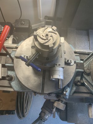
Just when I thought I had one too many rotary tables, I got an idea. I mounted a 4" rotary table on a 10" rotary table, offsetting the 4" by 1.4" from center.

If this stupid idea was going to work I would get the radius I needed for the vanes from the big table, and index 72* on the small table. Drew up kinda what I wanted the vanes to look like on the stainless with a sharpie since my Dykem was AWOL. Traced the edge with an end mill, looks like it was following along pretty good. Indexed the little rotary table 72* rinse and repeat.

In order to get the taper on the vanes, I had to move the Y axis .200 and rotated the little table 10* before I started indexing 72*. Worked pretty good

Took the little table off and milled out the center section. I know why this stainless was in the scrap bin. Shop dog said the milled finish wasn't worth its weight in dog food. This stainless was non magnetic which is what I really wanted for obvious reasons. Thought it was 304, but I usually get a good finish with 304.

I was hoping that I was going to have to remove some of the bored center depth, but that was not the case. I noticed online that one of the HAAS pumps has a spec of .007 clearance between the vanes and the top of the pump housing so I shot for that. Unfortunately, I had to make a shim to hit that number. Missed it by .012 so I surface ground one.


Looks like everything is fitting together OK, the pump housing has no pitting of substance. This evening we will test it and if it works, clean up the housing and get it ready for paint. But for now my thermometer is showing 105* in the shade so Shop dog and I headed in for a cold beer.

More news at 11
Grinding noises, but free. Put power to the 1/8 horse 220V 3 phase motor and it came to life. Looked like it was going to clean up OK so I ordered some sealed bearings to replace the shielded ones. Easy enough to install, they come out without much resistance. Started cleaning up the pump housing that evening and discovered the impeller was not going to make it. Cast aluminum or cast zinc, it had corroded through in a couple places and the center bore was pretty much gone. Probably not going to find an impeller for a 1979 Taiwan made bilge pump so I thought I would build up the pits and holes with JB weld and machine it back. Started down that path.
Shop dog took one look at it and said "Call me when your ready to start using all these machines you got." Certainly didn't have the patients to continue down the playdough road. And if I did, how long would it last with a 1/16" keyway for a drive pin? Probably not long.
I don't 3D print, so how can I make an impeller with curved vanes like the original?
Pretty sure I didn't have enough of the original impeller left to model from.
What should the new one be made out of? Delrin, aluminum, steel, stainless? Delrin would have been fun, but again, 1/16th keyway. Aluminum or steel would work, but not a great environment for either.
I had a .500 piece of stainless in the drop box that was 2.5" diameter, the original impeller (or what was left of it) was 2.20. The machined portion of the pump housing measured 2.22 so I hoped 2.20 is a good number.
Still flying blind, I figured the radius of the original impeller vanes was around 1.4 inches. 5 vanes, 72* each.
Turned down the stainless to 2.20". Bored the center to .3145" and cut a 1/16" keyway. Driving a 1/16th broach with a 20 ton press is like trying to drive a straight pin with a sledge hammer, but we got it done. The slot is extra deep because the shaft does not have keystock inserted. It looks more like a small metal pin or nail pressed into the shoulder of the shaft where it is turned down from .500 to .315.
Just when I thought I had one too many rotary tables, I got an idea. I mounted a 4" rotary table on a 10" rotary table, offsetting the 4" by 1.4" from center.
If this stupid idea was going to work I would get the radius I needed for the vanes from the big table, and index 72* on the small table. Drew up kinda what I wanted the vanes to look like on the stainless with a sharpie since my Dykem was AWOL. Traced the edge with an end mill, looks like it was following along pretty good. Indexed the little rotary table 72* rinse and repeat.
In order to get the taper on the vanes, I had to move the Y axis .200 and rotated the little table 10* before I started indexing 72*. Worked pretty good
Took the little table off and milled out the center section. I know why this stainless was in the scrap bin. Shop dog said the milled finish wasn't worth its weight in dog food. This stainless was non magnetic which is what I really wanted for obvious reasons. Thought it was 304, but I usually get a good finish with 304.
I was hoping that I was going to have to remove some of the bored center depth, but that was not the case. I noticed online that one of the HAAS pumps has a spec of .007 clearance between the vanes and the top of the pump housing so I shot for that. Unfortunately, I had to make a shim to hit that number. Missed it by .012 so I surface ground one.
Looks like everything is fitting together OK, the pump housing has no pitting of substance. This evening we will test it and if it works, clean up the housing and get it ready for paint. But for now my thermometer is showing 105* in the shade so Shop dog and I headed in for a cold beer.
More news at 11