How to measure/replicate an internal taper?

MikeInOr

Registered
Registered
Joined
Jan 1, 2018
Messages
1,211
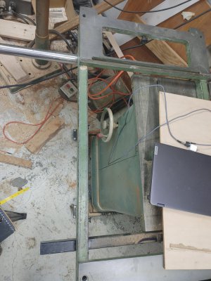
This is the out-rigger to my sliding table saw.
20240207_184138.jpg


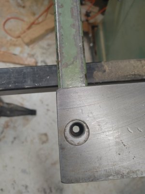
The two tapered holes at the top and bottom of the picture are where the fence mounts to the sliding table. I do not have the fence or the pins that go into these holes. The bottom hole is an eccentric for adjusting the fence square to the blade.
20240207_184022.jpg

I need to make the tapered pins that go in these holes. How do I figure out/replicate the taper I need for cutting new pins on the lathe?

The fixed hole is .609" at the top wide part of the taper.
20240207_184504.jpg

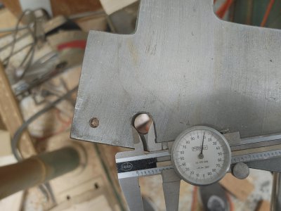
It is .553" dia at the bottom of the hole.
20240207_184527.jpg

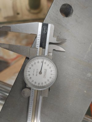
The hole is 1.53" deep (the thickness of the table).
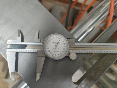
20240207_184552_HDR.jpg


The eccentric hole appears to be a steeper taper and has a ridge about 3/4 of the way down the hole making it much harder to measure.

I am tempted to drive a soft wood dowel (or maybe a candle stick?) in the eccentric hole, mount the dowel in the lathe then set the compound slide angle to closely match the compressed wood taper.

Any suggestions would be appreciated!
 
Last edited:
Most likely this would be a standard taper pin . But you do have have the measurements and could trig it out out easily . Being a saw and not needing to be precise I think you could figure this out . I'm going to make one very soon so Ill have questions also . :grin:
 
Grease the hole and plug it, then pour in some melted metal (old car wheel
weights?). Pop the plug out when it sets. Coathanger wire inserted as a handle?

I've used plaster of paris, too, in making replicas of things that need to fit.

Chuck the taper replica in your lathe, center it, and adjust the compound until it's parallel.
 
With your numbers, you have .22" taper per foot. No trig needed to cut a mating taper, just angle your compound until you touch a test bar at one point and get a .028" gap (half the difference) after feeding in by 1.53" (table thickness). It's a lazy solution that takes a little bit of fiddling to set the angle, but it works.

My preference would be to use two gauge pins that fit the bore and a height gauge.
 
Grease the hole and plug it, then pour in some melted metal (old car wheel
weights?). Pop the plug out when it sets. Coathanger wire inserted as a handle?

I've used plaster of paris, too, in making replicas of things that need to fit.

Chuck the taper replica in your lathe, center it, and adjust the compound until it's parallel.
This is my thought as well. Cerrosafe (brownells.com) is made for this type of application.
Whatever you do, it's likely you'll have to iterate if you want a tight fit. Consider turning a spud to your best estimate (or @pontiac428 's) then trying it in the hole with some Prussian blue and seeing if you need to adjust. Alternately, do the same thing with the 'real' piece, but then file to a good fit.

GsT
 
A simple and cost effective way to measure an internal taper is to face a short section of rod which will fit inside the large diameter of the taper.
On one end, turn a diameter smaller than than the large diameter but large enough to engage the small diameter of the taper. The plug is inserted into the taper, small end first and a dial indicator is zeroed on the opposite end. The plug is then reversed, and the dial indicator reading with it in contact with the small end is noted. You now have two diameters within the taper along with the distance separating them. Subtract the smaller from the larger and divide the difference by the length of the plug and you have the taper in "/".
 
In practice the above post has a few subtleties.
First, you have to be able to remove the plug and reverse it. This would most likely involve moving the indicator to provide clearance and you have to be able to return it to the same spot. If you have a DRO, using the carriage, yo can return the carriage to the same reading. With a DRO, you can also use a dial test indicator and return carriage to a zero test indicator reading and take the distance from the DRO reading. Without a DRO, set a carriage stop and return to the stop.
Second, in order to obtain an accurate measurement, the plug should remain concentric with the spindle axis so care should be taken when measuring.
Third, the precision of the measurement depends greatly on the distance between the two diameters so the length of the plug should be as long as practical.

Tom Lipton, OxTools, did a YouTube video on this method.

Edit. Fourth, it is important that the ends of the diameter are sharp.
 
Seems like a straight bore & pin would be a better solution. That taper is going to lock and be a PIA when you are trying to rotate the eccentric.
I had an SCM slider, 8'+ stroke & 16" blade. Straight pins! Very good saw.
 
Third, the precision of the measurement depends greatly on the distance between the two diameters so the length of the plug should be as long as practical.
I think you want the plug to register on the extremes of the internal taper, so you want the diameters of the plug to be significantly different. Other than for aid in establishing concentricity, the absolute length of the plug shouldn't matter as it gets subtracted out.
 
Back
Top