How To Measure The Diameter Of A Spindle Taper?

Joe Pitz

Registered
Registered
Joined
May 7, 2015
Messages
269
Hello all,

On my Clausing L-00 spindle and chuck.

I am having some run out issues on my chuck and adapter. Also some taper when I turn some round stock in just the chuck.

I have put a dial test indicator on my spindle, both when running and when hand turning the spindle and the run out is within .0005.

When I mount the chuck and perform the same run out test I get run out from .005" - .010"

When I turn round stock in just the chuck, I get .004" taper, smaller diameter, at the bar end away from the chuck.

I called Clausing and they sent me a service manual section.

It indicates that either the spindle collar is worn or the spindle nose taper is not true.

I took my adapter and put it on my mill and ran a dial indicator around both bearing surfaces and they are true to .0005".

I placed some plastiguage on the bearing surfaces of the adapter and mounted the adapter to the spindle.
The clearance was .002 on the rear bearing surface and .003 -.005 on the front bearing surface.

Now I need to determine how to measure the taper on the spindle nose. (again when running the dial test indicator on the spindle, there is very little run out).

What I now need to determine is if the spindle taper is worn.

If I can eliminate either the spindle nose or the spindle collar, my cost to repair will be less.

Can anyone tell me how to accurately measure spindle diameter taper on the spindle nose?

Thanks


Joe
 
Joe,
If I understand correctly, you are experiencing a larger runout when measuring a test bar mounted in the chuck. This is normal for most chucks. Unless you have a TruSet or similar chuck, three jaw scrolling chucks are just not that accurate. That is why machinists use four jaw chucks and dial in their work or turn between centers. Your spindle runout looks to be close to what I would expect to see. Your chuck runout is also typical. Better grade chucks will have less runout but you will pay dearly. There is a chance that your chuck was poorly fitted to the backing plate and that can be corrected. There is also possibility that the chuck jaws are worn if it is an older chuck and that can be corrected. Be aware that in most cases, you will only be accurate at one diameter. That is the nature of the scrolling mechanism and why machinists mount their work by other means. It sucks but that is the way it is.

Taper is another matter and indicates that the lathe ways are not parallel to the spindle axis or they are twisted. There are lots of discussions concerning tapered turnings and how to correct them. You should get the same taper whether your work is mounted in a chuck or in the spindle ( a Morse taper collet, e.g.). A worn or badly fitted spindle assembly will manifest itself in poor quality turnings, not in tapered turnings.

I would not expect PlastiGage to give you an accurate representation of clearances. It is meant for measuring bearing journal clearances where you can place thousands of psi of pressure on the PlastiGage material. I doubt that you can come close to that kind of load in your setup.

Bob
 
Joe,
If you are trying to determine if your Morse tape socket is correct, that is a difficult task to measure accurately enough to mean anything. Probably the best way would be to blue a known good male Morse taper and insert it into the socket, rotating slightly to seat it. When you remove the taper, you should see fairly uniform rub marks over the tapered surface. If you have a ring at one end or the other and the remainder of the taper looks untouched, then it would indicate an inaccurately ground taper. External tapers can be measured more easily but to do so accurately enough is also difficult. The common method is to measure the diameter at two positions a known distance apart. The taper is determined by the difference in the diameters which can be fairly small.

There was an energetic discussion of the measurement of tapers in this thread. http://www.hobby-machinist.com/threads/quick-measurement-of-small-taper-angle.34055/#post-288420

Bob
 
Thanks Bob, To give you some more info. I went through a very serious leveling session. I set up the lathe with a level and then turned a piece of stock. The taper started out around .010". I then keep on adding shim material on the low side and was able to get the taper down to .004" but no further.

According To Clausing the headstock is not adjustable. I am aware of the run out issues of a 3 jaw scroll chuck. I am more concerned about fixing the taper problem.

I do not have a Tru-Set chuck. I have a brand new Bison chuck. I purchased a new adapter plate and turned the plate myself on the lathe. The only issue I am trying to determine is, is my Spindle collar crooked or is my spindle taper worn, which according to the service manual would cause the taper.

There is one more issue that may be causing the problem, the diameter of the chuck adapter on the smaller bearing surface may be incorrect.

Thanks

Joe
 
Bob, Not trying to determine a Morse taper. My lathe has a L-00 spindle and the spindle nose is tapered. I am currently trying to calculate what the smaller diameter is so I can mic it.

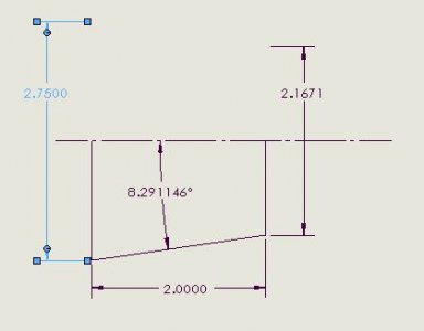
Outer diameter is 2.750" Width of taper is 2" and taper is 8° 17' 50". I am trying to find an online calculator that will allow me to calculate the smaller diameter so I can mic it.

This way I can determine if the spindle nose is worn. I will more than likely have to replace either the Spindle or the Spindle collar.

Trying to eliminate one or the other.

Thanks for the help

Joe
 
There is always a problem with accurately miking the small end of the taper because determining precisely where you are on the tape is indeterminate. One method which will work is to turn a short bushing with two different diameters on the ends and of a known length. You then seat the large end on squarely on your taper and zero an indicator. Then reverse the bushing and seat the small end and remeasure the the position. It works best if you have a DRO but it can be accomplished with other measuring tools. Tom Lipton from OxTools did a YouTube on the technique a while back. If I understand you, the taper has a large end diameter of 2.750" and its length is 2" and the taper angle (single side) is 8 deg. 17 min. and 50 sec. or 8.291146 deg. The small diameter should then be 2.750 -2*tan(8.291146)*2. The first "2" is because the distance calculated is for one side and you need to double it. The second "2" is length of the taper. That calculates to 2.1671 for the small end diameter.

If you need to measure an internal taper, you can use the same procedure by turning a shaft with different diameter ends.

Be aware that the accuracy of the measurement can be no better than your ability to measure the difference in the two diameters. In this case, it is about .6" so if you can measure to +/-.001", your relative error could be as large as .002/.6 or .3%. This would mean a possible error of .03 deg. in your angle determination.

Bob

Taper Dimensions.JPG
 
I would be very hesitant to blame the L taper. There is no movement between the taper mating surfaces. No way really do get wear, unless someone is off and on with chucks and fixtures many times a day for years. That spindle taper should be hardened, and take years of use with virtually no evidence of wear. It must be scrupulously smooth and clean, as must the mating taper and registry shoulders if used.

The method mentioned above about using bluing to check the taper condition will work on the L tapers as well. Remove the key and without using the nut, mate up the tapers with a slight twist, and look for even contact.

On a side point, despite a damaged taper or really much of anything, a turned shaft will represent the true axis of the spindle/bearings. Even if the chuck had 0.030 runout when chucking a piece, when turned, it should be straight, and have negligible runout. I think you are looking at the wrong area for your problem.
 
Hey Everyone, My logic may be incorrect. Here is some more information on the L-00 spindle and collar.

Maybe I am trying to read too much into this.

I guess I am just trying to fix my taper issue.

http://www.tools-n-gizmos.com/specs/Lathe_Spindle_Mount.html

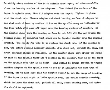
Enclosed is also the section on the service manual on how to test the spindle and collar.

I performed the dykem test. I did not get much dykem transfer on either bearing surface of the adapter. But I was able to see a nice pattern on the spindle where the outer bearing surface imprinted on the spindle. What I did not see was any transfer in the dykem from the inner bearing surface of the adapter. So that lead me to believe that it could be either the spindle collar, the spindle nose and now I am wondering if the inner bearing surface on the adapter might be off.

So If my thought process is incorrect then this is where I can use the groups help.

Thanks everyone, you are always so helpful to me.

Joe

manual.jpg
 
Back
Top