How To Read Backlash In Fractional Or Decimal Form?

Pumice

Registered
Registered
Joined
Jul 25, 2015
Messages
5
I understand what Backlash is and how to measure it but I don't know how to translate that measurement into fractions of an inch or metric decimal notation.

Below is the backlash of my lathe.

The divisions on the handwheel that operates the leadscrew/x-axis goes from 0 - 4 .
Distance between 0 to 1 on the dial measures 3/4 inches .

Each numbered mark is divided into 10 marks ( i.e. there are 10 marks between 0 and 1)
The backlash comes to 2 . 2 (i.e. 2 marks after the 2 on the dial) .

Now how do I read this in inches or metric?

The backlash on the compound rest comes to 1 mark short of 2.9

-

The cross-slide has finer divisions than the leadscrew and the compound rest.
0 to 1 on the dial measures 3/8 " . There are 5 marks between each numbered mark (i.e. 5 marks between 0 and 1)
The backlash is 1 + 3 marks . So it is 1.6?

-
How do I read these backlash measurements as fractions of an inch or in decimal notation ?


Thank You
 
I'm having difficulty understanding some of your descriptions. When you say that "Distance between 0 to 1 on the dial measures 3/4 inches.", are you measuring the actual distance between the marks on the dial, or are you measuring how far the carriage actually travels when you rotate from 0 to 1??? I really don't know of any kind of practical lathe whose carriage would move 3/4" when the handwheel is turned between two numbered divisions! It sound like you're putting a ruler against the dial, which won't give you any useful information.

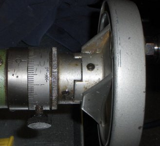
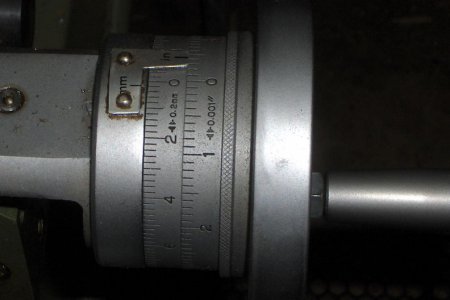
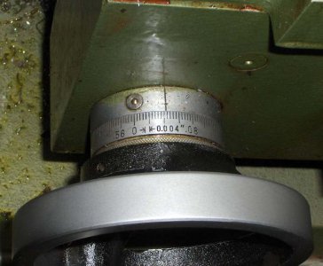
Try turning the handwheel all the way around. Somewhere (probably near the zero) there should be some kind of notation about what amount of motion is represented by the smallest division. I've attached a couple photos to illustrate. With that information in hand, you should be able to figure out the backlash from the number of small divisions you have to move before there's a response from the compound or cross slide. It will be in thousandths if you have an inch lathe or millimeters if your lathe is metric.

HPIM3772.jpg HPIM3771.jpg HPIM3770.jpg

My apologies if I've misinterpreted your description, but this is the best guess/interpretation I can give you
 
Put a dial indicator on the cross slide, turn the handle in one direction and note the indicator position then set the handle dial to zero, turn the handle in the other direction until the indicator moves and note the position of the handle dial, the difference is the apparent backlash which is the lead screw thread lash + any lateral lash in the lead screw mounting mechanism. For all useful purposes this is a measurement of overall lash as seen on the machines dials. As far as "converting backlash into decimal" it is built into the machine on the dials.

ALL decimal dimensions are by nature fractions with a common denominator ie, .001 is 1/1000, .010 is 10/1000 and so on. As for metric conversion 25.4 millimeters = exactly 1 inch (for all practical purposes), the measurement standards have been adjusted over the years to make this work.


Please note that many lathes utilize a cross feed lead screw that has twice the lead of the longitudinal gear set, for instance if one wishes to turn an OD in the Z axis (toward or away from the chuck) at .010" Per Revolution set the gears to that feed rate, when facing the same part (in the X axis) on such a machine set the feed rate to .020" Per Revolution to achieve the same feed rate. This often causes problems when facing as many do not realize that the feed rate has now been reduced by 1/2

Some manufacturers use a Radius cross feed lead screw and simply double the number of divisions on the cross feed dial to account for this, which is a good thing as the feed rates remain equal.
 
Last edited:
And backlash can differ along the length of the screw.
 
At the general area where I use the cross slide the most, here is the backlash reading, you can read how many thou is swings at both ends before the thread engages, dial indicator monitoring the tool post movement confirms the backlash manifested on the dial, well close enough for government work.


That is part of the backlash but there are other contributors. To make an accurate assessment, you need to set up and indicator as WreckWreck has suggested. That takes into account other factors such as lost motion due to frame flex, gib play, etc. If you haven't already established the dimension of your dial spacing, the dial indicator will tell how big each division is.

Bob
 
0-1 with ten lines in between is one thousands per line , the #1 is 10 thousands.
2 and 2 marks I am assuming is in thousands would be 2 = twenty thousands and 2 marks is two thousands that would equal 22 thousands is close to 1/64''
in mm 2.2 = 5/64'' ?
fractions
.015 = 1/64
.031=1/32
.0625 =1/16''
.125 =1/8''
.250 =1/4''
 
Last edited:
I'm having difficulty understanding some of your descriptions. When you say that "Distance between 0 to 1 on the dial measures 3/4 inches.", are you measuring the actual distance between the marks on the dial, or are you measuring how far the carriage actually travels when you rotate from 0 to 1??? I really don't know of any kind of practical lathe whose carriage would move 3/4" when the handwheel is turned between two numbered divisions! It sound like you're putting a ruler against the dial, which won't give you any useful information.

Try turning the handwheel all the way around. Somewhere (probably near the zero) there should be some kind of notation about what amount of motion is represented by the smallest division. I've attached a couple photos to illustrate. With that information in hand, you should be able to figure out the backlash from the number of small divisions you have to move before there's a response from the compound or cross slide. It will be in thousandths if you have an inch lathe or millimeters if your lathe is metric.

View attachment 108501 View attachment 108502 View attachment 108503

My apologies if I've misinterpreted your description, but this is the best guess/interpretation I can give you

Yes I put a flexible tape measure over the dial and the distance between the 0 and 1 on the leadscrew handwheel and the cross-slide handwheel measures 3/4". There is no notation stating what each division is.

I don't have an indicator , but it is something I will get in the near future.
 
Last edited:
If I am looking at your scale in the photo. 0-1 with ten lines in between each line is one thousands the #1 is 10 thousands.
fractions would be
.015 = 1/64
.031=1/32
.0625 =1/16''
.125 =1/8''
.250 =1/4''

So if the inch tape measure reads 3/4" for the distance between the 0 and 1 on the handwheel and the backlash appears to be 2.2 then how many thousands of an inch is that?
 
So if the inch tape measure reads 3/4" for the distance between the 0 and 1 on the handwheel and the backlash appears to be 2.2 then how many thousands of an inch is that?

Forget the inch tape. It has no bearing on the reading. On each of your dials, you have a scale factor. i.e. ->| |<- .001" means each division is .001".

To determine the amount you moved the carriage, cross feed, or compound, count the number of divisions move and multiply by the scale factor to get the distance moved.
 
Back
Top