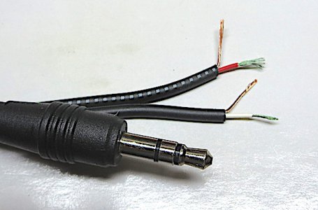
How to solder to these round lugs?

Franko,

I refer to flux as radio flux as opposed to a flux that would contain zinc chloride(corrosive) which generally used for galvanized materials and such.
Kester is a well known brand in fluxes used in radio work. There are two kinds that I use routinely on electronics. One is Kester 186
which contains rosin and the other is Kester 961E which does not. I have had good luck with both depending on the application.
Hopefully this clears up any confusion on the subject.
 
Thanks, Joe. Totally clear, now. :) Kester multi-core is what I have. It has always been great for small connections.

RJ, the lugs are tiny. The big outside lug is so small I'll be lucky to get a pencil tip on it. I have a pencil tip with a flat that I plan to use. That'll be as much contact as is available. I've found that a bit of melted solder on the tip helps increase contact with small lugs.

I'll make a run to Altex after my dentist appointment this afternoon. Maybe they'll have a 3.5mm stereo repair jack with regular tabs.

The jack I'm replacing is not broken. I just want to shorten the wire. It has a 10' wire on it, which is just too long and unwieldy. I cut the old jack off and stripped the wires to see which goes to tip and ring. Strangely, I'm not getting any continuity from any of the wires to ring or tip. Ground does have continuity to the sleeve. That's weird, because the jack was working.

[edited to add: I tinned the wires and was able to get continuity.]

As near as I can determine the standard, Red is ring (right) and white is tip (left).

IMG_1018.JPG
 
Last edited:
I use a soldering pencil with 33 watt element. Use rosin core electrical solder, it comes in varying diameters. Pre tin the ends and push the center wire down to the bottom of the tube. Usually there is a small hole down there. The other two are attached to the two tabs. A short touch and add a little solder and with a steady hand remove the heat. Put a little insulator between the wires going to the tabs if required and be sure to put the sleeve on first before soldering and in the right way!
 
The shield wires go to the outside tab.
 
I'm not sure what that means, George.

I tinned the wires and was able to get continuity. So, all is good.
 
I have never seen lugs like that on a phono plug. I wonder if the plug was even designed for solder connections. Maybe it is intended to mate with some sort of wire termination. I might look for another plug with more accessible lugs for soldering if I had to do the work.

Be sure to use old-school leaded electronic solder... Kester 44 or similar. The lead free stuff has a higher melting temperature.
 
Pierre, I plan to use small heat shrink to isolate the connections and reinforce the grip on the wires. It will add a little strain relief.
The center lug is not a hollow tube like banana and RCA jacks.

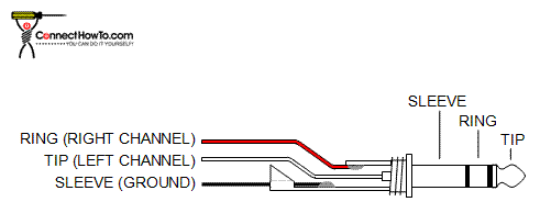
Here is a chart for stereo plug nomenclature and wiring.
Some stereo jacks have 4 connections. I'm guessing they are for balanced plugs and jacks.

Stereo-Jack-Wiring-Diagram.gif
 
Last edited:
I have never seen lugs like that on a phono plug. I wonder if the plug was even designed for solder connections. Maybe it is intended to mate with some sort of wire termination. I might look for another plug with more accessible lugs for soldering if I had to do the work.


Jon, I thought that was possible, too. But, the jack describes itself as a solder type.
 
This is a .125” diameter pin called miniature while the 1/4” plug is the phone size.
 
Back
Top