How to wire a DC Injection Brake on a 3-Phase motor

bbarenz

Registered
Registered
Joined
Jan 18, 2021
Messages
2
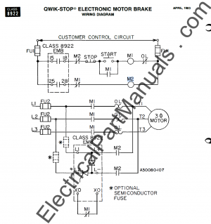
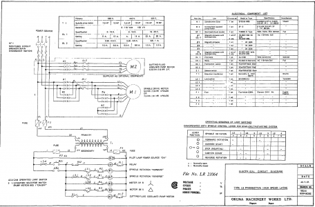
I'm trying to install a Square-D 8922 EMB 20/480 DC injection brake on an old Okuma LS lathe with a 3 phase (240V) motor. The module didn't come with instructions but I found some online but they aren't very comprehensive and leave me with a lot of questions. The diagram from the DC Injection Brake manual is below as well as the wiring diagram for the Okuma lathe. I'm fairly confident the main power wiring is correct (L1,L2,T1,T2). I connected I5,I8 in series with the Start/Stop circuit however I'm not sure where 25,28 and X0,X0 (on the DC Injection Brake) are supposed to go. I originally thought X0 was a capacitor however it shows the same M1 symbol as show in series with 25,28 so I'm not sure what M1 is meant to be. (X posted on Practical Machinist)
 

Attachments

  • Capture.PNG
    Capture.PNG
    137.2 KB · Views: 15
  • Capture2.PNG
    Capture2.PNG
    199.1 KB · Views: 14
You will need another separate braking contactor to apply the DC to the motor windings when the motor for/rev contactors are open. There are three switched control terminals on the brake module 0, 1 and 2. Terminal "1" is the control power supply for the contactors, when the module is deactivated this is connected to power that goes to the spindle that operated the forward reverse contactors. The "0" terminal is connected to a separate braking contactor that is connected tot he motor and applies DC between two motor windings. This provides an interlock that the motor cannot be started until the braking module times out and the DC braking is completed per the timer. Typically there is an AC control transformer that provides power to the contactors, this may be 24, 120 or 240VAC, so the braking contactor must be rated for the same voltage as the current contactactor. There is also the option of fusing the DC braking unit as shown in the attached document.
 

Attachments

  • dc injection motor brake instructions.pdf
    388.4 KB · Views: 17
Thank you that was very helpful and answered a lot of my questions. I'm used to IEEE symbols and when you said NEMA symbols that was a big help as well. I've been reading that DC injection brakes still take a while to stop and tend to overheat the motor if doing a lot of starting and stopping. A mechanical brake seems to be the best solution but I was avoiding going down that path due to the cost and complexity but that may still be an option if I don't get this brake working. I'll update with progress.
 
If there is room to install it maybe consider a Baldor Brake/Clutch module. Brake goes on same time clutch goes off so work shaft stops immediately and motor can slow down at its own pace.

 
Back
Top