How was this oil fitting made?

ballard26

Registered
Registered
Joined
Jun 11, 2020
Messages
8
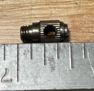
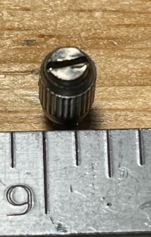
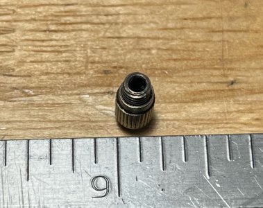
I'm hoping to make a few oil fittings from a Pratt & Whitney No. 3 Miller(http://lathes.co.uk/prattwhitneymiller/). Here are some photos of one;
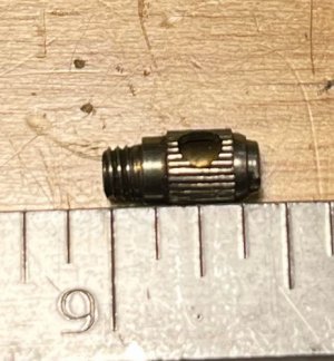
side_closed.jpegside_open.jpegtop.jpegbottom.jpeg

The vertical head and dividing head would've had a bunch of these. Unfortunately the previous owner of the mill I have removed all but one leaving a bunch of threaded holes that chips can work their way in. I've looked online to see if this was a commonly made part at some point and to see if I could buy a few extras, but had no luck. So I have screws blocking the holes for now and am hoping to make new ones as I like the design.

It seems to be constructed in two parts. An inner body that is threaded into the castings and has a blind hole along its length and a cross-drilled hole for oil passage. I.e,
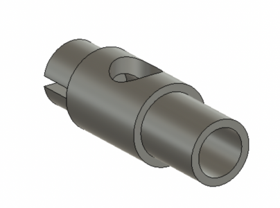
Screen Shot 2023-11-06 at 12.25.07 AM.png


And a knurled outer body that freely rotates around the inner body to block the oil hole when not being used. I.e,
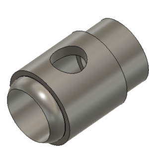
Screen Shot 2023-11-06 at 12.35.11 AM.png

While the outer body can freely rotate around the inner body it appears to be permanently attached to the inner body. I'm not sure how this was done. My best guess is that the the radius feature in the outer body was originally machined as a thin-walled cylinder then pressed in a die with the inner body already in place to form the radius feature and and permanently attach the two.

Is this possible? And/or is there an easier way to make this part?
 
I offer an alternate design idea for you to consider.
Make the threaded part essentially the same as the sample.
Rather than making the sleeve, use CapPlug closures slid onto the screw to cover the filler hole.
Size the screw body diameter to a snug fit with a standard size CapPlug.
The caps are available in RED color which will help identify the oil ports.


To answer your original question, I suspect the sleeve part, reduced diameter end, is swaged in a die to shrink the OD of the end circular element into a groove in the screw.
 
Sort of like Extropic said. I think there’s a hydraulic crimp or a swage (or both) happening at some point in the manufacture of that part.
 
Basically, make the collar and use a snap ring to hold the rotating collar against the head.
 
Imagine, if you will, the inner part of the assembly as a piston, circumferential groove fitted with a piston ring.
Then, the outer part, with the piston ring compressed, will fit over the inner.
If, however, the outer part has an inner groove, it will capture the ring, and never release.
Another design variant could use nitinol instead of close-tolerance springy ring components.
 
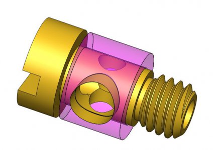
Here is a fairly easy project for a lathe. A swiveling side port. The brass colored part can be made on a lathe in a single setup witha secondary operation of cutting the cross ports and the screwdriver slot. The ports aren't critical and can be done on a drill press and thew slot could be cut with a hack saw if a mill isn't available. The port in the magenta barrel can be made as needed. seals are made by means of two gaskets, one on either side of the barrel. The assembly can be made either so it locks in place when it is tightened or so it is free to pivot after installation depending upon the diameter of the ported cylinder relative to the thread diameter,
Swiveling Side Port.JPG
 
Here is a fairly easy project for a lathe. A swiveling side port. The brass colored part can be made on a lathe in a single setup witha secondary operation of cutting the cross ports and the screwdriver slot. The ports aren't critical and can be done on a drill press and thew slot could be cut with a hack saw if a mill isn't available. The port in the magenta barrel can be made as needed. seals are made by means of two gaskets, one on either side of the barrel. The assembly can be made either so it locks in place when it is tightened or so it is free to pivot after installation depending upon the diameter of the ported cylinder relative to the thread diameter,
Nice! This is very clever. It would definitely simplify making the part. I'll try making one this weekend and see how it looks/works. Will post pictures to this thread of one when it's been made.

To answer your original question, I suspect the sleeve part, reduced diameter end, is swaged in a die to shrink the OD of the end circular element into a groove in the screw.
Sort of like Extropic said. I think there’s a hydraulic crimp or a swage (or both) happening at some point in the manufacture of that part.
Yeah, the original part is definitely has the outer sleeve crimped, swaged, or otherwise deformed around the inner part of the body. I can't really figure out which part of the outer sleeve has been deformed though as there aren't any witness marks or signs where it was deformed. I thought that maybe the inner body could've been deformed outwards into the outer sleeve as well, but the inner bore looks smooth and consistent. I may still try to make it as it was originally at some point since it seems interesting, but it's out of my skill-set/knowledge at the moment.

Imagine, if you will, the inner part of the assembly as a piston, circumferential groove fitted with a piston ring.
Then, the outer part, with the piston ring compressed, will fit over the inner.
If, however, the outer part has an inner groove, it will capture the ring, and never release.
Another design variant could use nitinol instead of close-tolerance springy ring components.
Good idea. Not too sure if I'd be able to machine an internal groove in a 1/8"-ish bore with my current set of tools. However, once I get better at grinding my own tooling this would be something I'd like try.

A couple of o-rings should work.
Basically, make the collar and use a snap ring to hold the rotating collar against the head.
I'll definitely be keeping these retaining methods in mind for future projects. Thanks!
 
Sort of like Extropic said. I think there’s a hydraulic crimp or a swage (or both) happening at some point in the manufacture of that part.
The outer element is knurled, though, so we ought to consider also that a knurling-like operation
using smooth rollers could shrink the metal for locking; it'd only take some fiddly machining of the
end of the outer element's hole aperture to make a feature to engage an inner-element groove.

I have at least two kinds of crimp pliers that'd work on aluminum or brass for the right diameters.
 
Back
Top