IGaging DRO power supply questions

Investigator

H-M Supporter - Gold Member
H-M Supporter Gold Member
Joined
Jun 8, 2016
Messages
603
I read some older threads about the IGaging DRO's, and wasn't sure if there was any new information to be had. I'm wanting an electric power supply for my DRO's on my RF30. Not sure if the what I understand is still correct or not but.....Do the wall wart power supplys still cause interference? Has anything corrected that yet? I'm hoping I can run all 3 axis on one power supply, is that too much? Is there a better way to get around the dead battery issues?
 
The DRO's use 3.3v so a wall wart is not quite the answer, I don't see any putting out that voltage.

As to interference, in my experience the issue seems to get worse with an external supply. Any grounding issue in your machine will send spikes through the frame and thus to the metal scales.
I had to install ground wires between motors and frame and isolate the metal scales of the DRO's from the machine frame. A filter across the motor on/off switch is next although the problems are mostly gone by doing the frame isolation. If you can 3D print the mounts or make them from Delrin that you are golden in that area.
 
An LM317 voltage regulator can easily be used to make a 3.3 volt supply from a 5 volt wall wart. At its simplest, the LM317, two resistors, and a couple of capacitors are all that's required. It will easily run three scales. It can be done for under $1.

I use the iGaging DRO's with the TouchDRO display on a tablet. I use a 12 volt wall wart to provide power to trhe circuitry. It is regulated to 5 volts and dropped down to 3.3 volts for the scale pickups. I had problems with interference from the lathe motor . My scales are grounded to the lathe. Some capacitors in the scale pickups solved that problem. There is a thread on HM that thoroughly decribes this modification.
Thanks for this. I forgot I had some LM317's and just made a circuit with a 22/36R for 3.3V for my DRO's
Never could get one of the older style igaging DRO's to stabilize though.
 
Thanks for this. I forgot I had some LM317's and just made a circuit with a 22/36R for 3.3V for my DRO's
Never could get one of the older style igaging DRO's to stabilize though.
Can I make a suggestion? Using such low value resistors is unnecessary current drain. The resistors are to provide a voltage reference they don't need to sink high current. I would use a 22k/36k combination, or a 2.2k/3.6k

Sent from my SM-S908E using Tapatalk
 
Thanks but I just shrink wrapped and taped it all up. Why do the low values cause a current drain and why is it an issue?
 
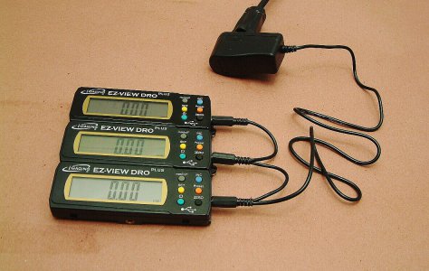
Before I upgraded to TouchDRO I used three individual wall chargers similar to that shown above. The TouchDRO “box” now powers all three through the USB cables.
 
If you use a wall wart, get one with a linear PS vs. a switching PS. Linear is cleaner noise wise and usually offers a little better isolation from the mains. 9 or 12VDC out would be good with an LM317 because you need a 2 or 3 volt differential between the input and output to stay in regulation. Most linear wall warts I've taken apart just have a transformer, bridge and filter capacitor. The switching style are very light. So if your DC wall wart has some weight, it most likely is a linear power supply. There are low dropout regulators out there for smaller differentials. I have some Chinese scales that I want to try, but the positive of the battery is connected to metal frame of the read head i.e. positive ground. I've read that this is difficult with a power supply. I guess I better get to it before these scales become antiques. Using batteries have not been too much of an inconvenience. Unlike most of you, I'm a very casual hobby machinist. I probability, on average, only create a pound of chips per year.

Some great links:
 
Thanks but I just shrink wrapped and taped it all up. Why do the low values cause a current drain and why is it an issue?
Because according to ohms law I=V/R.

At 3.3v those two resistors will be drawing 66mA.

Not a lot but also not insignificant. To put it on perspective your 36ohm resistor is drawing 0.157W of power. That's half the rating of a 1/4W resistor and over current for a 1/8W resistor. Both will feel pretty warm with the 1/8w probably burning out.

At the end of the day it is just inefficient. You could achieve the same with a 36k 22k resistor combination and drain 1/1000 of the power draw.

Sent from my SM-S908E using Tapatalk
 
Back
Top