

-
Welcome back Guest! Did you know you can mentor other members here at H-M? If not, please check out our Relaunch of Hobby Machinist Mentoring Program!
You are using an out of date browser. It may not display this or other websites correctly.
You should upgrade or use an alternative browser.
You should upgrade or use an alternative browser.
Info needed for installing/setting up pm940m
- Thread starter tim81
- Start date
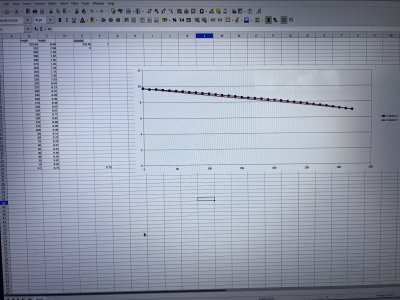
For my z-axis gib the thickness chart on the good granite l. Length was a bit less then 320mm How to measure the angle and width?If you really go to all of this trouble also measure the wide width (sharp corner to sharp corner) a function of length. If when you put it back and you measure how much of the gib is sticking out of the hole (big end) then after some calculations you will have an idea of how big the gib hole is nominally.... Mine is the top curve in the following plot. By the way, my 940M's way corners are at 55 degree. Some other machines are at 60 degree. This relates to the side corners angles of the gib. I have to go. Have fun.
View attachment 468804
Attachments
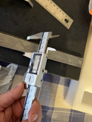
Tim, I worked it all out at one point. I think I gave some equations earlier. If you know the angle of the way, the gib edge angle should match it or be a little short of touching at the corners. Then if you know the width at the large end and thickness taper angle (thickness from one end to the other, and the length gives you this.) Then all of the dimensions of the gib are defined and you do not need to make other measurements except to confirm things.Length was a bit less then 320mm How to measure the angle and width?
Draw a trapezoid representing the top (big) end of the gib. (You can think of this as just matching the trapezoid shape between the way and the saddle way. So the gib would ideally just fill this gap every position down the saddle way.) Then using the taper angle at any point along the gib all of the dimensions are determined. The similar shaped trapezoid at the small end will be smaller in all dimensions. This same trapezoid shape is essentially the difference in the shape of the way, which does not change with length, and the shape of the matching way in the saddle which changes along the gib length.
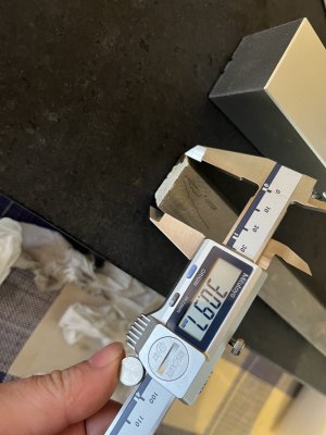
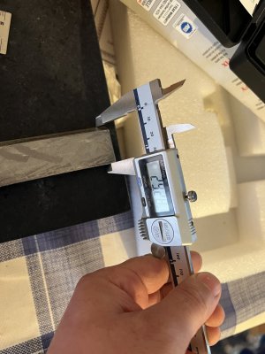
In your photo you have measured the distance between the points/corners of the trapezoid, but parallel to the flat thickness of the trapezoid. You could have also measured the actual distance from these two corners. Fortunately, the corners of your gib are not too rough or broken or ground off. So you plot looks pretty nice. I suggest you measure the thickness along the length. If your measurements are accurate then the two should agree, when you do the trig to compute the other from one set of measurements. If the edge of your gib, corners are not perfectly sharp or are broken off then your corner to corner measurements will predict the wrong thickness by some amount.
By the way, my old South Bend lathe uses Brass gibs (softer than steel and can be harder than Al). This way, they machine wears the gibs and not the ways so much.
The cast iron gib that came with my 940M is awful. Even the 55 degree corners look like they were made by making lots of little edge step milling passes so that the part did not have to be clamped at an angle to make a 55 degree surface cut. In concept a gib only has to touch at a few points to hold the saddle square. In fact, in concept one could have only two short trapezoids, one at each end of the saddle slot with a connecting rod to hold them in place. However, having limited surface would mean they would wear quickly. So, it would be find if there were a number of holes drilled through the gib so that one could screw it down during a milling or grinding process. With the taper one would just sort of grind off the material and a portion of the screw heads would be sacrificed in the process. I do not have a surface grinder so if I ever make a new gib I will probably do it on the mill.
Dave L.