Input On My Pieced Together Rpc

Nope you do have to have 2 banks of run caps. No diodes in a run cap. Just the cap. Wiring them together would indeed put a dead short across L1 to L2 and of course that would be bad.

Cap sizes are going to run 10 to 15uF per horsepower of the idler motor.

Now too much capacitance can be as bad as too little or no capacitance. When the capacitance is too high the L1 to L3 and L2 to L3 voltage increases, and it can be significant. I have seen it up near 300 volts when experimenting with RPC's. Obviously you don't want that so you will have to adjust your values to get your voltages right.

Thanks! I kind of figured so after looking at the tabs closer, I've got a bunch of 10uf on order so I'll be experimenting soon. Was thinking about running two banks equaling 30uf then adding smaller increments from there for my 5hp idler,

I assume I may see some changes when a load is added to the rpc?

Thanks again.


Sent from my iPhone using Tapatalk
 
Nope you do have to have 2 banks of run caps. No diodes in a run cap. Just the cap. Wiring them together would indeed put a dead short across L1 to L2 and of course that would be bad.

Cap sizes are going to run 10 to 15uF per horsepower of the idler motor.

Now too much capacitance can be as bad as too little or no capacitance. When the capacitance is too high the L1 to L3 and L2 to L3 voltage increases, and it can be significant. I have seen it up near 300 volts when experimenting with RPC's. Obviously you don't want that so you will have to adjust your values to get your voltages right.

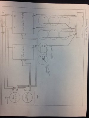
Ok here's my schematic with all the components I believe you guys were recommending. Anxious to hear if you guys think this looks ok. Assume the start and run caps are sized appropriate that I will be doing with your recommended starting point with balance tuning from there .

IMG_2604.JPG


Sent from my iPhone using Tapatalk
 
there are many ways to skin the same cat.
i'd consider making a line connection to the start caps, otherwise you'll have a hard time charging the start caps
in your configuration, the contactor must close in order to charge the caps.
it's ok for the run caps, but, you'll need an initial charge to start the idler

Ok you stumped me again. Can you explain what you mean by a line connection to the start caps?

Thanks


Sent from my iPhone using Tapatalk
 
You'll supply an unbroken connection to 1 power leg
The cap output can be broken with a relay
 
You'll supply an unbroken connection to 1 power leg
The cap output can be broken with a relay

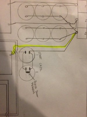
Like this? Add a jump from the start contactor that goes straight to the l3 output in parallel with the start capacitors. The way I illustrated it would only see power while holding the normally open start switch then that and the start cap circuit would be completely out of play when the button is released and the l3 would only see power through the l1-l3 and l2-l3 run caps.

IMG_2606.JPG


Sent from my iPhone using Tapatalk
 
maybe on the other side of the contactor and use the contactor to make/break the cap output
 
maybe on the other side of the contactor and use the contactor to make/break the cap output

Alright so the third leg likes full time supply from one of my real legs in addition to the run capacitor circuits.

Sounds simple enough, wife just sent me a picture of all the usps boxes on the porch so I should have everything to start wiring tomorrow when I get home.

Thanks again for the recommendations


Sent from my iPhone using Tapatalk
 
Back
Top