- Joined
- Feb 2, 2014
- Messages
- 1,068
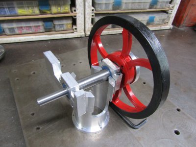
This is a photo that I found online showing a model engine.
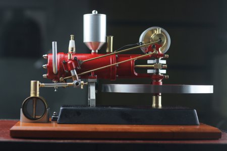
The motor wagon engine has a horizontal flywheel mounted in the rear of the three wheeled auto. It was believed to be the first practical automobile in the world.
There are many sites on line showing the engine and explaining some of the features but very little technical information. All of the videos I have seen are of model engines and many searches have not produced any drawings of the engine. There is a company in Germany that is selling engine castings with plans but that is out of my price range.
So I will just wade right in and see what comes out in the end. All measurements and sizing will be taken from what looks about right in the pictures so who knows what the end product will be.
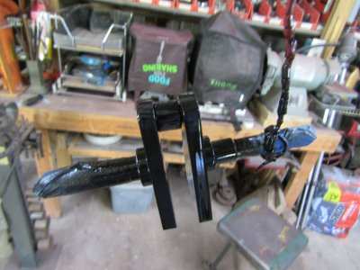
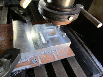
I had a 5lb weight that I had started machining for a previous engine a few years back but it had many hard spots and several voids so it went in the drawer until now.
I like to use stock that I have on hand to get started as it gives me incentive to continue.
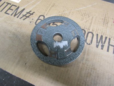
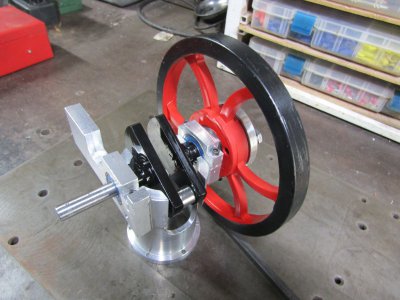
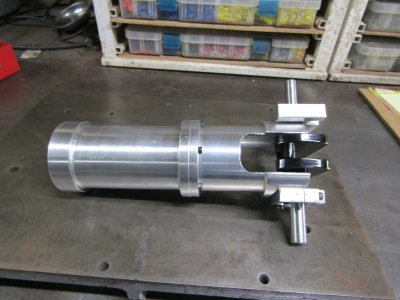
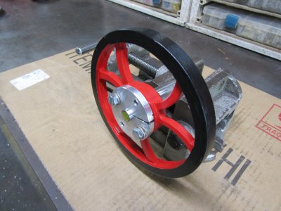
Some more machining, some sculpting, some hole filing, and some paint later.
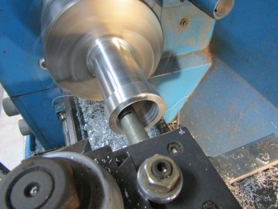
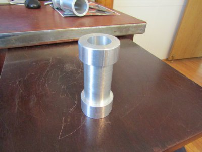
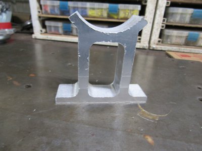
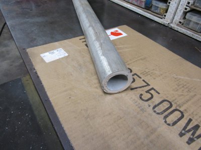
I had this aluminum tubing about the right size and cut off a piece.
I whittled it down to this.
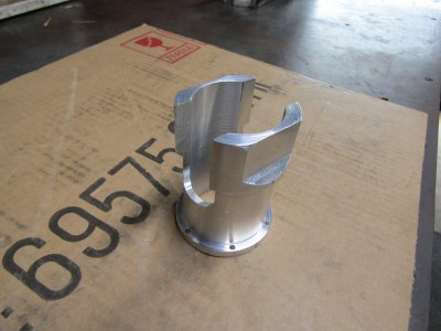
The crankshaft will be attached to open end of this part and the cylinder attaches to the other end.
Thanks for looking
Ray

The motor wagon engine has a horizontal flywheel mounted in the rear of the three wheeled auto. It was believed to be the first practical automobile in the world.
There are many sites on line showing the engine and explaining some of the features but very little technical information. All of the videos I have seen are of model engines and many searches have not produced any drawings of the engine. There is a company in Germany that is selling engine castings with plans but that is out of my price range.
So I will just wade right in and see what comes out in the end. All measurements and sizing will be taken from what looks about right in the pictures so who knows what the end product will be.
I had a 5lb weight that I had started machining for a previous engine a few years back but it had many hard spots and several voids so it went in the drawer until now.
I like to use stock that I have on hand to get started as it gives me incentive to continue.

Some more machining, some sculpting, some hole filing, and some paint later.

I had this aluminum tubing about the right size and cut off a piece.

I whittled it down to this.

The crankshaft will be attached to open end of this part and the cylinder attaches to the other end.
Thanks for looking
Ray


