- Joined
- Dec 3, 2014
- Messages
- 497
I thought this may be a helpful reference for others looking to solve the common issue of having the x axis scale mounted on the side of the cross slide where it interferes with the tail stock and is exposed to coolant, oils and damage.
I did this on a mid sized lathe, a Colchester Master 2500 but it has been done on many smaller lathes, and there are even microDRO options out there that allow invisible mounting on even the smallest of lathes typically in use today.
This project came about when my brother was considering buying the lathe. He demanded that I promise to install the DRO on the lathe within a week or so of his taking possession of it in order for him to buy it because the main arpon wheel lacked any scale. I agreed because I already had ordered a 2 axis system with linear glass scales with travel lengths of 150mm (5.91") & 1000mm (39.37") for our previous 12x37" lathe. I figured that system should fit this new one just okay.
So the master 2500 is a 13x40 lathe. The slimline glass scale was neither slim nor long enough for the cross slide, and the read head to the middle of the saddle would prevent the tail stock from being abutted to the carriage as we normally use the lathe.
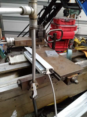
So I had to reconsider. I first thought to move the read head to the rear of the cross slide like this fellow did with his master 2500 below, while maintaining the scale at the side biased towards the rear of the cross slide. It would still interfere far too much.
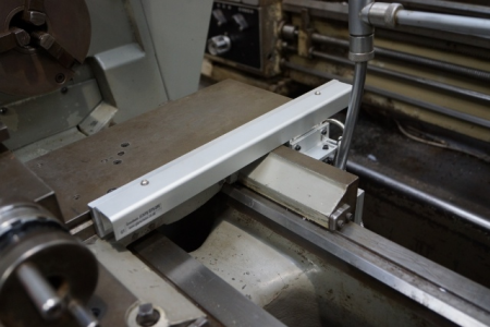
More on the solution I arrived at in a minute.
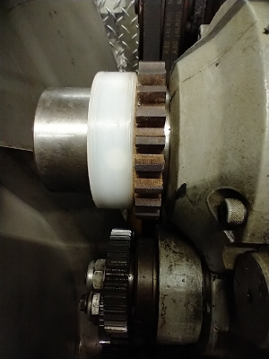
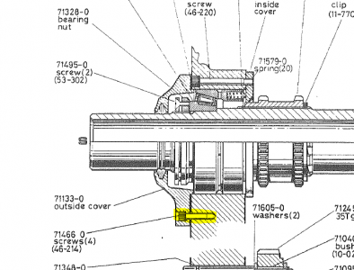
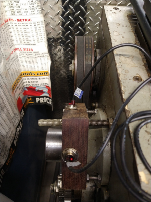
The z axis mounted to the rear of the lathe perfectly, but it is too short to allow the full travel of the carriage with no tail stock mounted. A reasonable compromise since we seldom turn parts that length. We will make a carriage stop for the left end travel limit. We can detach the read head if required or, and we can easily change this later scale if desired to long magnetic scale. Below is the scale prior to the installation of the cover, and the bracket to hold the read head. I put blocks under the scale because the bed was too hard to drill, and the blocks allowed me to use existing holes in the bed, and to use a shorter arm offset to mount the read head to.
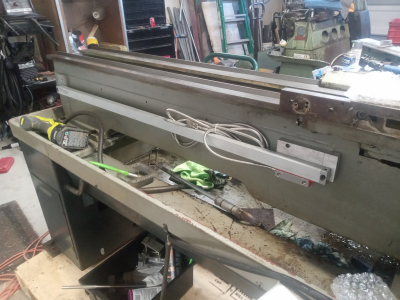
With the read head and cover installed. The coolant arm will mount to the upright vertical between the two cap screw heads.
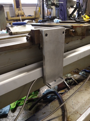
Now to the x axis.
I found a couple of threads on another forum where the owners of myford lathes embedded a magnetic tape in a groove on the underside of the cross slide. I immediately ordered 3 magnetic read heads with 1 micron resolution and 2 meters of magnetic tape. I'll use the excess on my own colchester chipmaster lathe.
I then played around with the placement of the tape and read head plus an extension block to accommodate the end of travel over the read head.
At first I was going to center the tape and read head like this, however this would have come too close to the splash guard and required a more complex block to mount the read head.
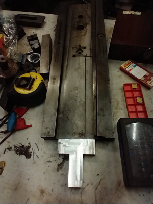
Instead I found that I could tuck the read head into this spot and directly mount it to the cross slide lead screw bracket. Nice and compact. This then placed the magnetic tape in a groove just inside the vee.
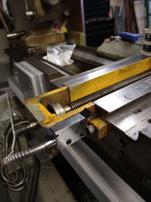
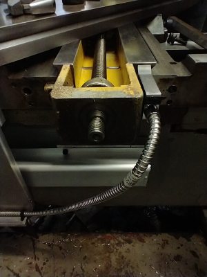
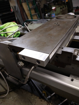
The completely assembled cross slide assembly and scale. Note the aluminum extension with a much smaller overhang and no tang on it. The small overhang accommodates the pocket and magnetic tape extension so that both the read head and wiper clear the end of the scale. This mounting as far as I know wont interfere with the tape turning attachment if I find one.
I did this on a mid sized lathe, a Colchester Master 2500 but it has been done on many smaller lathes, and there are even microDRO options out there that allow invisible mounting on even the smallest of lathes typically in use today.
This project came about when my brother was considering buying the lathe. He demanded that I promise to install the DRO on the lathe within a week or so of his taking possession of it in order for him to buy it because the main arpon wheel lacked any scale. I agreed because I already had ordered a 2 axis system with linear glass scales with travel lengths of 150mm (5.91") & 1000mm (39.37") for our previous 12x37" lathe. I figured that system should fit this new one just okay.
So the master 2500 is a 13x40 lathe. The slimline glass scale was neither slim nor long enough for the cross slide, and the read head to the middle of the saddle would prevent the tail stock from being abutted to the carriage as we normally use the lathe.

So I had to reconsider. I first thought to move the read head to the rear of the cross slide like this fellow did with his master 2500 below, while maintaining the scale at the side biased towards the rear of the cross slide. It would still interfere far too much.

More on the solution I arrived at in a minute.
The z axis mounted to the rear of the lathe perfectly, but it is too short to allow the full travel of the carriage with no tail stock mounted. A reasonable compromise since we seldom turn parts that length. We will make a carriage stop for the left end travel limit. We can detach the read head if required or, and we can easily change this later scale if desired to long magnetic scale. Below is the scale prior to the installation of the cover, and the bracket to hold the read head. I put blocks under the scale because the bed was too hard to drill, and the blocks allowed me to use existing holes in the bed, and to use a shorter arm offset to mount the read head to.

With the read head and cover installed. The coolant arm will mount to the upright vertical between the two cap screw heads.

Now to the x axis.
I found a couple of threads on another forum where the owners of myford lathes embedded a magnetic tape in a groove on the underside of the cross slide. I immediately ordered 3 magnetic read heads with 1 micron resolution and 2 meters of magnetic tape. I'll use the excess on my own colchester chipmaster lathe.
I then played around with the placement of the tape and read head plus an extension block to accommodate the end of travel over the read head.
At first I was going to center the tape and read head like this, however this would have come too close to the splash guard and required a more complex block to mount the read head.

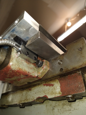
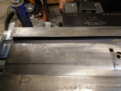
Instead I found that I could tuck the read head into this spot and directly mount it to the cross slide lead screw bracket. Nice and compact. This then placed the magnetic tape in a groove just inside the vee.


The completely assembled cross slide assembly and scale. Note the aluminum extension with a much smaller overhang and no tang on it. The small overhang accommodates the pocket and magnetic tape extension so that both the read head and wiper clear the end of the scale. This mounting as far as I know wont interfere with the tape turning attachment if I find one.


