Is this an aliasing thing, or some sort of defect?

WobblyHand

H-M Supporter - Diamond Member
H-M Lifetime Diamond Member
Joined
Dec 18, 2019
Messages
6,447
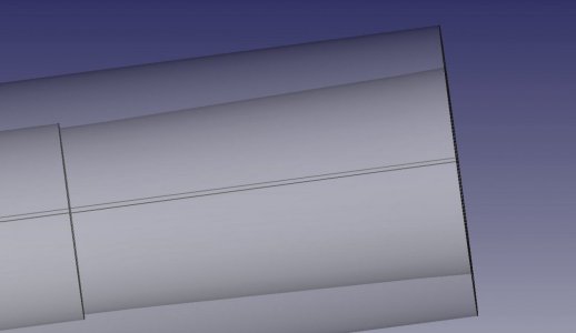
To solve the problem of my tapers not fitting, I made a model of the MT4 taper and the spindle socket of my G0772Z (G0602). I made the two bodies coaxial and slid one body into the other. (Done via changing the X axis attachment point of the sketch.) I made the socket transparent, and the taper opaque. Even when the mt4 tool is made invisible, the spindle taper seems to have flared out ends at the start and end of the taper. The sketch itself does not have this.

I have set the Anti-Aliasing to MSAA 8x, naively thinking this might be better, but the false flair seems to still be there. Have tried line smoothing, MSAA 2x as well and looks the same. Using orthographic rendering.

Anyone have an idea what is causing this?

apparent flared taper.jpg

mt4 in spindle.jpg
sketch of revolution.jpg
 

Attachments

  • spindletaper.FCStd
    30.3 KB · Views: 1
I can see what you mean.

I looked into sketcher (nothing obvious to help) and PartDesign preferences where there are options for line width and vertex size, but change from 2px to one did not help.

I noticed the TechDraw view shows the line smoothly, so played a bit more and found as you view your model from different angles, then "effect" appears to change and you can get different effects on top/bottom edge in same view.

You can see that the size of the "feathering" along the edges changes from large, as your model shows, to very fine at different 3D rotations.

This fits my belief that this is a FC rendering artifact (most likely where display precision, but not model precision is reduced for speed). So your model is actually precise.

Example of different view attached. If it still bothers you ask in the FreeCAD forums, or if you prefer, I can ask for you.

Another part of all this, is what is your next step? For example, use the tech draw dimensions to machine this yourself, our send to someone else to make, or use Path Workbench to output gcode? Answer to that influences whether this makes any difference.
 

Attachments

  • spindletape_dif_angle.jpeg
    spindletape_dif_angle.jpeg
    43.4 KB · Views: 6
I can see what you mean.

I looked into sketcher (nothing obvious to help) and PartDesign preferences where there are options for line width and vertex size, but change from 2px to one did not help.

I noticed the TechDraw view shows the line smoothly, so played a bit more and found as you view your model from different angles, then "effect" appears to change and you can get different effects on top/bottom edge in same view.

You can see that the size of the "feathering" along the edges changes from large, as your model shows, to very fine at different 3D rotations.

This fits my belief that this is a FC rendering artifact (most likely where display precision, but not model precision is reduced for speed). So your model is actually precise.

Example of different view attached. If it still bothers you ask in the FreeCAD forums, or if you prefer, I can ask for you.

Another part of all this, is what is your next step? For example, use the tech draw dimensions to machine this yourself, our send to someone else to make, or use Path Workbench to output gcode? Answer to that influences whether this makes any difference.
This was only an exercise for me to understand how a known good taper would fit in my threaded lathe spindle. I am having issues with some tooling not fitting properly. I spun a taper in my spindle causing some damage. I made this model to figure out what would happen. I can make the spindle transparent in the model, but I cannot do this in real life!

However, I was taken aback by the artifact. It makes me distrust the tool, and gives me pause. It makes me wonder if it always tells the truth. That is why I consider it serious. If I cannot trust the tool, then why should I continue using it?

There can be times when what one wants to see, is only visible in a certain 3d orientation. If there's an artifact, one cannot tell if there is a true error, or just an artifact. I do not subscribe to the idea that I should trade display precision for a fraction of a second rendering speed, especially for such a simple model. If there is such a knob, or adjustment, I'd like to change the defaults.

I'm not currently on the FreeCAD forums. As a relatively new user, with a whopping 3 months under my belt, I know little of the proper CAD terminology, so I don't even know how to properly frame the question. If you could bring it up there, I would appreciate it. Trust is an important part of a tool or software package. If the tool appears to lie, then users will distrust it, and perhaps abandon it. Believe, me, that was my initial reaction. What? I can't trust it?
 
I don't use FreeCad so I can't comment on its idiosyncrasies but in So0lidWorks and I expect any of the other modeling programs, the relationships are actually mathematical in nature. The visual output is just a representation for the user's benefit. In SolidWorks, if you closely at a relationship of a point on a line, it often will appear to not be coincident with the line. However, it is. If you set up your mathematical relationships properly, everything will be right.

OTOH, if you visually place a point on a line and don't mathematically fix it, either by establishing a relationship or using a snap feature, you can get into trouble and sometimes it is difficult to understand what is wrong. I got into the habit of locking down everything that I sketched so that the sketch was defined and not underdefined or overdefined. This prevents some hair tearing later on.
 
These surfaces are made from revolutions of sketches around an axis. The coordinates of the points in the sketches are all equation based from a spreadsheet that I entered in the program.

For instance, the small end of the taper in the sketch was computed in the built-in spreadsheet as
SmlEnd = SpindleLargeEnd/2 - TaperLength * tan(AnglefromCenter)
where all of these parameters are "variables" in a spreadsheet.

Unfortunately in the sketch graphic above, all one sees is the computed number. However, since I use the spreadsheet mode, every measurement is derived from the spreadsheet. It takes discipline to do it this way, but, I find it really helps you to parameterize your designs effectively. If one double clicks on the value, you can see the equation that gives that number.

FreeCAD warns you if the sketch is not correctly constrained, under, or over. It can be fun to work it all through, but it is very effective.
 
Based on this old post re tesselation, which recommends:
Edit -> Preferences -> Part Design -> Shape View -> Tessellation -> Maximum deviation ... ->

I think the default is .5%; you'll get smoother edges if you try something like .05 or maybe .02% at the expense of increased processing times ( but for simple models it's negligible).

I tested and it seems to remove the "false flair" and now the stepped edges are still present, but appear straight.

Make sure you open the Part Design workbench, before trying to set the preference, or you will not see them.

Described in more detail here in the FreeCAD wiki.
 
Based on this old post re tesselation, which recommends:


I tested and it seems to remove the "false flair" and now the stepped edges are still present, but appear straight.

Make sure you open the Part Design workbench, before trying to set the preference, or you will not see them.

Described in more detail here in the FreeCAD wiki.
Awesome! I will give that a try. Hopefully that option is in 0.19.2 stable. Yes, that does work! Is there a way to reduce the faceting of round objects? If one zooms in, one sees a circle consists of lots of straight line segments. Why I care - I have a chinese taper that is slightly out of spec. I am modeling inserting the taper into a MT socket, with faceting it is difficult to see if the taper is truly seated in the socket. I'd also like to measure (from the model) the gap due to the incorrect fit.
 
Last edited:
In the second link posted above, the wiki sates"

In order to display an object efficiently its surface is tesselated, i.e. it is displayed with some small deviations from it real surface.

So it is purely a way to "display an object efficiently" and the model is accurate.

I noticed that the size/number of jagged edges on the tubular sections/tapers changed to be quite smooth in some view angles and more jagged in other views (as per your attached model). Attatched is a very zoomed in example, which still has the original setting of 0.5% for tesselation, but had reduced edges from 2 to 1px.

If you are still concerned, maybe use the Draft WB to show a cross section and then measure there, given that your original model attached above clearly shows draft does not have the tesselation.

This actually might be best way to measure, as measuring on the smooth surfaces of the model will make it very hard to precisely place measurement points to get perpendicular distance and not at some angle. In my attached picture, I "eyeballed" the perpendicular measurement!
 

Attachments

  • spindletape_dif_angle3.jpeg
    spindletape_dif_angle3.jpeg
    20.3 KB · Views: 0
In the second link posted above, the wiki sates"


So it is purely a way to "display an object efficiently" and the model is accurate.

I noticed that the size/number of jagged edges on the tubular sections/tapers changed to be quite smooth in some view angles and more jagged in other views (as per your attached model). Attatched is a very zoomed in example, which still has the original setting of 0.5% for tesselation, but had reduced edges from 2 to 1px.

If you are still concerned, maybe use the Draft WB to show a cross section and then measure there, given that your original model attached above clearly shows draft does not have the tesselation.

This actually might be best way to measure, as measuring on the smooth surfaces of the model will make it very hard to precisely place measurement points to get perpendicular distance and not at some angle. In my attached picture, I "eyeballed" the perpendicular measurement!
I ended up changing the tessellation to 0.01%. That helped a lot. Then changed the anti-aliasing to MSAA 8x. Much better.

I use TechDraw, which allows cross-sections. It's tough to see microscopic details. The taper error of my bad adapter analytically was off by 2 x 0.109 mm at 59 mm. I was looking for a way to visualize that. It's amazing that such a small error can cause a taper to spin in your spindle, but I experienced it. I will have to look into a way of doing a detailed cross-section, if such a thing is possible.
 
Back
Top