Jet HVM728 Horizontal/Vertical Mill Electrical Panel Issue

ford65

Registered
Registered
Joined
Jun 10, 2019
Messages
3
Hello all,

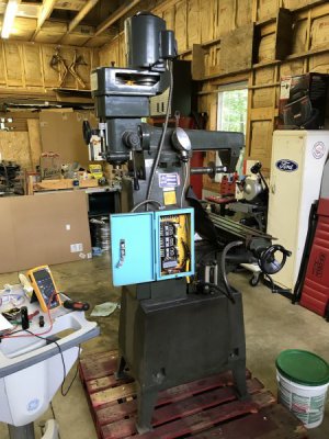
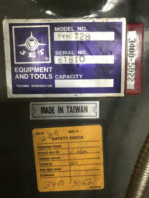
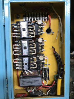
I'm new to machining (and learning a lot from this forum) and I recently purchased a Jet HVM-728 that was removed from service in a nearby VA Hospital welding shop. The machine looks to be in good shape but it appears as if it has never been cleaned in 30+ years! One big issue that I have to address is that when they took it out of service, they cut a great deal of wiring in the electrical panel. I have seen this happen on several pieces of electrical equipment removed from the VA, and it makes no sense to me why they do this. I’m certain they cut wires and removed a 14 position terminal block. I was just checking to see if there is anyone on the forum who has a similar machine and can help me out with this issue by taking some pictures of the inside of the electrical panel of their HVM-728. This might help in determining a sensible routing to this wiring mess I have acquired. Thanks for any help you can give me on this. (I'm not certain if the pics will post correctly, as I have little experience on posting pics!)
IMG_0301.JPG
IMG_0298.JPG
IMG_0303.JPG
 
Whoever clipped the wires did it on purpose to discourage bidders at the auction. Then they could buy for it for a song. No doubt they also have the wiring schematic.
Best bet is to contact Jet for a manual.
 
here is manuals that may help
the second and third manuals have wiring schematics
 

Attachments

  • HVM-728.pdf
    679.9 KB · Views: 33
  • HVM-728 OPERATORS MANUAL.pdf
    1.8 MB · Views: 39
  • HVM-728 OLD .pdf
    2 MB · Views: 31
  • HVM-728_OCRd.pdf
    705 KB · Views: 33
i owned a Trans World Steel VHM-728, a sister to the Jet-728


basically, you have 2 contactors that are responsible for directional control
you have one contactor that operates the coolant pump
the transformer creates the 110v control voltage for the operation switches
 
It's a 3-phase machine isn't it? I would just get a VFD to run it, then you can just tear out all the old contactors and wiring, run the VFD directly to the motor
Problem solved
 
Amazingly this machine has a label on the electrical panel door that says Pre Wired 110V. That may be a blessing and a curse, as my shop is a half mile from the nearest 3 phase source and I can only hope it will have enough grunt on 110V to get the job done once I get the motors turning!

Thanks Ulma Doctor for posting the manuals with the schematics. Fortunately, prior to my purchase of the machine, I found your post several years ago regarding your 'sister' machine purchase and the attached manuals. I probably would not have purchased my machine had I not found that information here. I also called Jet requesting their version of the manual (thinking it may be a little less Taiwanese and a little more English) and they kindly supplied me with the exact same manuals!

I understand the contactor switches and have determined which switch controls which motor, and where the outputs come off of the switches. However, on the overloads, the pump contactor and vertical contactor both have a pigtail of a white wire that was cut with no id number on them. These are on the same terminal as a cut wire marked '0' and I believe this is a neutral wire from the transformer. The overload on the horizontal contactor (the center one in the box) only has the cut wire marked '0' and is missing the wire with no id number. There is also a pigtail of a white wire that was cut with no id number under the far right position on the top terminal block, and this is under a cut wire marked '0'. (I have tried to attach a photo with these wires circled in red.) Maybe the unmarked wires had '0' markers on them that fell off and maybe they were jumpers, but I can't guess where they terminated on the other end. The fact that there are 3 unmarked white wires and not 4 makes me wonder if I'm guessing wrong about them being jumpers. The individual who cut the wires and removed the terminal block did not clean out the bottom of the panel box, and there were no wire markers rolling around in there. Also, why would the factory have taken the time and materials and stacked 2 wires on the same terminal, if they both run back to the neutral? I feel like I may be overlooking something really simple here, and a pic or two of an electrical panel on a working HVM-728 would clear it up instantly. Anybody got one?
IMG_0301-Marked3.jpg
 
if you were to send a message to @TAWP Tool ,
he may be able to provide you with a photo of the electrical enclosure.
he has the Trans World Steel VHM-728 now
 
I know this is an old thread, but it is very cool- Hoping for some response..
I acquired a JET HVM-1PFB which is in the same family as this, but a little larger.
Thank you, Ulma Doctor for the manuals. They have been helpful- although a bit weak in content.
Looking for some advice- I'm very close to cutting metal with it, but I discovered a problem that I'm not sure the best way to attack.
The rotation of the head is wonky. When everything is locked down, the head still rotates a couple of degrees. I'm hoping this can be corrected without needing unobtainable parts. If it came down to it, I could probably get it perfectly vertical then weld it, but that would be a last resort.
The manuals Ulma Doctor shared are not very clear as to how I would go about disassembly of this, and I'd rather not be guessing.
Any advice is appreciated!
i'm glad the manuals were of some value to you

when you say that the head is rotating a few degrees when locked down,
are you referring to the Spindle Housing to the Ram interface (part# 051 and 517 respectively (pages 11&12)
OR
the part #153 Base housing/ 051Ram interface (pages 11&12)
OR
am i missing the boat completely?

i can offer this, there are 4 t-bolts on either rotation point described above ,that lock these surfaces down
 
Back
Top