- Joined
- Apr 21, 2015
- Messages
- 582
{UPDATE: Here are the final drawings and here is the Fusion360 3D model. I've started a series of construction articles on my blog.]
Making or purchasing a ball-turning accessory seems to be a very popular activity among people with our interests.
Every time it comes up on these forums, my friend @Jimsehr mentions his super simple ball turner, but I've never seen anyone actually make one before. I think many are confused by the blurry photos and the terse replies that Jim has posted (sorry, Jim!).
I've been told I have the gift of gab, and I'm not one to shy away from explaining something I barely understand, so I wrote up my experience building Jim’s design on my blog. Note that I've included a downloadable 3D Model (Fusion 360) as well as a pdf of dimensioned drawings (for my lathe specifically, but they should be easily adapted to yours).
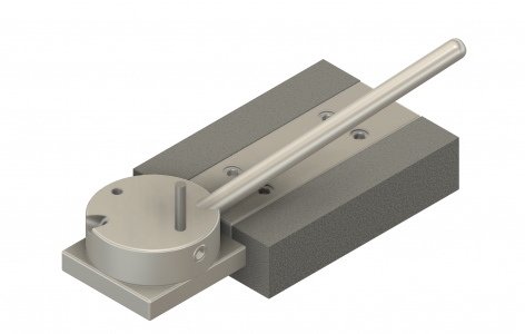
Here's the ORIGINAL design I settled on after several discussions with Jim:

Design notes:
Making or purchasing a ball-turning accessory seems to be a very popular activity among people with our interests.
Every time it comes up on these forums, my friend @Jimsehr mentions his super simple ball turner, but I've never seen anyone actually make one before. I think many are confused by the blurry photos and the terse replies that Jim has posted (sorry, Jim!).
I've been told I have the gift of gab, and I'm not one to shy away from explaining something I barely understand, so I wrote up my experience building Jim’s design on my blog. Note that I've included a downloadable 3D Model (Fusion 360) as well as a pdf of dimensioned drawings (for my lathe specifically, but they should be easily adapted to yours).
Here's the ORIGINAL design I settled on after several discussions with Jim:

Design notes:
- It mounts in the tee-slot on a lathe compound. Set screws hold it rigidly in place. Not all of us have "boring tables" or a place to mount tooling on the cross-slide, so mounting on the compound is quite convenient.
- The design is quite flexible. With 1/8" cutters and a 1.5" diameter by 1/2" thick puck on my 10" lathe, I can cut up to a little larger than 1" balls. The distance from the top of the puck to center height is the limiting factor. Larger diameter cutters might need a larger puck for the set screw to have enough threads engaged.
- The pucks have a boss on the bottom that registers into a bored and reamed hole in the tee base. The radii are fixed, not continuously adjustable, but it's easy to make multiple pucks at once for different radii (I'm making pucks 1", 3/4", 5/8", and 1/2" diameters -- smaller ones are easy enough to cut with a form tool).
- Cutters can be pretty much any diameter. The top is ground perfectly flat (sharpening is trivial).
- The pucks aren't even screwed into place, they just rest in the bored hole. Since all the cutting forces are directly tangential into the long axis of the cutter, and the cutter is directly supported below by the tee base, it's quite rigid with absolutely zero forces trying to lift it out of the hole.
- I've decided on one radius per puck. There are two holes: one is positioned so the distance from the center of the puck to the inner side of the cutter is the desired radius (for cutting balls). The other hole is for cutting concave radii with the distance from the center of the puck to the outer diameter of the cutter being the desired radius. Center height is set simply by loosening the set screw in the side, then tightening when you've got it spot on.
- I've decided to make two holes for the handle to screw into, 180 degrees apart from each other. I've made it angled for clearance, but whatever tickles your fancy is fine (I know: it needs a ball on the end). Note that you need almost a full 180° spin of the handle to turn a ball on a thin neck. The two locations are to allow a full 360 degrees of access in case something interferes for part of the cut.
- It uses a tangential cutter with zero rake and zero relief. Many don't think such a cutter will work, but I assure you it works fantastically well (see the blog article for details). It won't face, but it will turn fixed convex and concave radii into the side of a rod just fine.
Last edited:

