Just trying to understand

ltlvt

H-M Supporter - Sustaining Member
H-M Platinum Supporter
Joined
Aug 29, 2019
Messages
515
I have a Snap-On YA-205 mig welder that I am trying to repair. It is another victim of the Mud Dauber gang. I will not go into detail of how I hate the little Mud Demons just to say they are totally destructive. The welder was working fine and thanks to them they packed mud in places that should not have mud. So now I am after several years about to tackle the job again this winter. I am going to try to post the pdf file to the control schematic and as you will see the parts list on the left at the bottom and on the right is some Electronic lingo that is past being Greek to me. Hopefully someone is going to pity me and explain what that actually means. These welders were originally built by Century
Electric a division of Lincoln. But like anything else with time on it all the old guys have either left the companies or passed on.
The original problem was it would not feed wire. I talked to the rep at Century, and he told me to replace a transistor which I did and then it blew the main power fuse. Not sure why it blew the fuse but I am sure I can track that down easy enough, but I do need help understanding the Electronic Lingo. Hope the pdf file helps.
 

Attachments

  • 880_113_666.pdf
    101.6 KB · Views: 28
I can't weld and never really been around welders old or new. But looking at the diagram the transistors drive a motor. I'm assuming that is the feed motor. Those are in a push pull configuration I think which drives the motor forward and reverse. Most of the other parts in the diagram are logic devices (IC2) and Darlington drivers (IC1). Taking a wild guess there is a logic failure which caused both transistors to turn on at the same time which caused a short and blew the fuse. Hopefully it didn't take out a transistor again (assuming my guess is correct). I would think IC1 & IC2 are simply plugged into dual inline sockets therefore easily replaced. I'm including links to the datasheets for those parts I suspect.
IC1 https://www.ti.com/product/ULN2004A#params
IC2 https://www.ti.com/lit/ds/symlink/c...30328&ref_url=https%3A%2F%2Fwww.google.com%2F
Hopefully replace those and you may have something. Double check the transistors before you power it up.
There are many things which could be the problem and I must admit my first guess usually isn't correct. But I think that is a good starting point.
Good Luck!
 
I can't weld and never really been around welders old or new. But looking at the diagram the transistors drive a motor. I'm assuming that is the feed motor. Those are in a push pull configuration I think which drives the motor forward and reverse. Most of the other parts in the diagram are logic devices (IC2) and Darlington drivers (IC1). Taking a wild guess there is a logic failure which caused both transistors to turn on at the same time which caused a short and blew the fuse. Hopefully it didn't take out a transistor again (assuming my guess is correct). I would think IC1 & IC2 are simply plugged into dual inline sockets therefore easily replaced. I'm including links to the datasheets for those parts I suspect.
IC1 https://www.ti.com/product/ULN2004A#params
IC2 https://www.ti.com/lit/ds/symlink/cd4093b.pdf?ts=1698735430328&ref_url=https%3A%2F%2Fwww.google.com%2F
Hopefully replace those and you may have something. Double check the transistors before you power it up.
There are many things which could be the problem and I must admit my first guess usually isn't correct. But I think that is a good starting point.
Good Luck!
Thanks Chip. I have checked transistors and diodes before but have forgot how I did it. What is the easy with my DVM. It has a diode mode. BTW there is no reason for the feed motor to run in reverse. It has 2 modes of feeding. A push button to spool wire out while holding the button down and the variable speed controlled by the gun trigger and wire feed potentiometer. Thanks very much for your kind response.
 
Last edited:
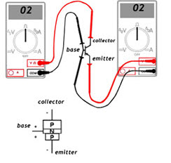
Connect the negative probe of the multimeter to the base output (usually it is a black probe), and the positive (red) first to the collector and then to the emitter. Obtaining a value in the range of~500 -1500 Ohm confirms correct operation of the transistor.1698811057023.png
 
Connect the negative probe of the multimeter to the base output (usually it is a black probe), and the positive (red) first to the collector and then to the emitter. Obtaining a value in the range of~500 -1500 Ohm confirms correct operation of the transistor.View attachment 464658
Thanks
 
If the problem really is caused by dirt from the mud daubers, that could cause a failure in the transistor control logic and turn both transistors on which could blow a fuse. With the power disconnected, try cleaning up the control board with alcohol and a small brush. Especially in the area of IC2. Look at both sides of the circuit board. Dry the board thoroughly.

With a circuit like this, if you are not familiar with testing transistors, it is best to buy a couple each of Q1 and Q2 and replace them both at the same time and try again. If the fuse blows again after replacing both Q1 and Q2 then it probably isn't the transistors, although they may give their life due to another problem on the circuit board or even a short circuit off the circuit board. The transistors are relatively cheap though. Buying the integrated circuits and replacing them all would be cheap and easy too. Be sure to put them into the sockets in the right direction...
 
I would replace the following if they are socketed:
IC2 -CD4093
IC1 -ULN2004a
Test and if necessary replace:
Q1 -TIP142
Q2 -TIP147
Use a solder sucker or solder wick when removing the transistors- try not to overheat the foil tracks on the board or they will lift.
Sometimes it's easier on the board to just clip the leads of the part you want to remove and then heat and pull the stubs, then
clean the hole of solder with a sucker or wick- if the part tests good you can solder wire "stilts" on to the part and re-install it..
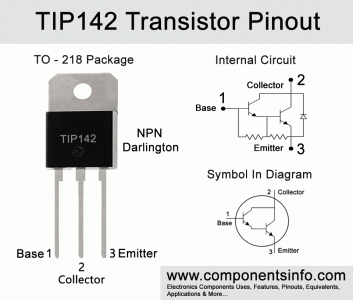
Best way to test darlington power transistors is dynamically- I'll do a sketch, stay tuned

tip142-transistor-pinout-equivalent.gif
 
Last edited:
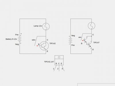
Make a test jig with a cordless drill battery or other 12v source and a small auto bulb: (reverse battery polarity for TIP147)
Connect the collector to the base with a jumper wire momentarily- the bulb should light
Make it a quick test so the transistor doesn't heat up too much
If the bulb lights without the jumper wire the transistor is shorted. If lamp doesn't light at all the transistor is open.
TIPtest.jpeg
 
Last edited:
Back
Top