Keyway Machining on a Lathe

vtcnc

Admin
Staff member
H-M Lifetime Diamond Member
Joined
Jun 29, 2014
Messages
4,059
As part of my CNC Lathe build, I need to install some pulleys on the spindle drive. The easiest method for making a key way in a pulley is to broach the feature into to part. I'm facing two challenges in using this traditional method: no arbor press and no broach tooling.

O.k., alternative methods are:
  • to use a slotter attachment on a milling machine. I'm in the middle of 7,000 projects, can't take on one more,
  • hand file,
  • hand scraping.
The issue with hand work is that these pulley are going on a CNC lathe spindle. I can't afford to mess up these parts, and I'm not confident in my hand skills to get a perfect keyway with no slop allowed in my spindle drive.

There is an alternative, that sort of uses a slotter type arrangement, but without all of the horsepower behind a machine.

Here is my setup:

View media item 98071
Several keypoints that allow this to work successfully:
  • You must be able to lock your spindle,
  • You must be able to accurately locate a horizontal reference across the workpiece,
  • You must be able to index the cutting tool on the crosslide,
  • You need to allow for clearance of the tool to pass through the workpiece while being held in the chuck,
  • You need to grind a tool accurately,
  • You need to be able to locate the tool in such a way that it is index perpendicularly to the wall of the pulley.
You can see in the gallery photo above that I have a spindle lock on the Atlas 10. The cutting tool is set in the tool holder in such a way that I can pull the tool towards me at the desired cutting depth. When you grasp and indicate the workpiece be sure your chuck jaws allow for the tool to clear through the part. Also notice the flat on the shank of the tool, this allows me to clamp the part in the tool holder and maintain perpendicularity to the wall of the sleeve or pulley.

Here is how I indicate a horizontal reference:

View media item 98072
In this photo, you can see how I used the combination square to do three things simultaneously:

  • Find center of the part,
  • Find horizontal reference across the part, using the spirit level,
  • Marking the horizontal reference using the straightedge.
Once I had the scribe mark to indicate a horizontal center across the face of the part, I could go in with the quick change tool post and make fine adjustments to dial in the center of the HSS tool cutter to the horizontal reference line.

From there, I took small bites (.005-.010) with some cutting oil until I reached my desired depth. In these photos, I could hog out .008-.010 passes in the brass sleeve. In the steel pulley, I couldn't bite more than .005" at a time, so that required many passes. This was done by advancing the carriage longitudinally along the lathe bed.

View media item 98073
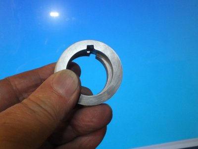
Result was nice, straight keyways to the desired depth. I was skeptical, but these ended up with snug fits, if not near perfect sliding fits with a little fine filing.

View media item 98074
 
Excellent description, very clear. Could you show us a close up of the tool?
 
Yes, I used a mini-lathe as a "human powered shaper" to cut a couple keyways. I know it can be done.
The small errors were due to not locking the spindle.
 

Attachments

  • 5 Two finished key spindle spacers for 7 by 16 lathe.jpg
    5 Two finished key spindle spacers for 7 by 16 lathe.jpg
    73.4 KB · Views: 23
I've done that before. It sucks. Ran out of elbow grease in the middle and had to finish the next day.
 
Used the tailstock screw to push my 'broach' through my work. No strain. (pushing against the back of the "Aloris" type tool holder.
Well that seems like an obvious improvement to the process (now that you pointed it out)
 
Excellent description, very clear. Could you show us a close up of the tool?
I'll get a picture in the morning. But basically think of a parting tool geometry.

Used the tailstock screw to push my 'broach' through my work. No strain. (pushing against the back of the "Aloris" type tool holder.
That is a good suggestion. I hadn't thought of doing that! Next time for sure!
 
@vtcnc nice work, very ingenious levelling of the workpiece!
Is that just a standard boring bar with a purpose ground HSS bit?
 
@vtcnc nice work, very ingenious levelling of the workpiece!
Is that just a standard boring bar with a purpose ground HSS bit?
Thanks!

It's just a piece of 1/2" steel rod. Probably 12L14. A piece of 1/4" HSS steel bit was ground while mounted in the boring bar and mounted in the toolholder. This achieves several things: 1) keeps my hands clear of the wheel, 2) keeps my hands cool and 3) helped me maintain all of the rake and relief angles I was going for. Don't ask what the angle were, I was just eyeballing them but I would say 10-15deg on the cutting face, bottom and side reliefs, all negative from the cutting face.

The only disadvantage to this is that you can't feel the heat building in the tool bit. So I would count off about 5-7 seconds of grinding and then dip in the oil just to cool off the bit. This saved me from overheating and losing any temper or hardness.
Thanks! Is the hole in the boring bar round or square/rectangular?
 
Back
Top