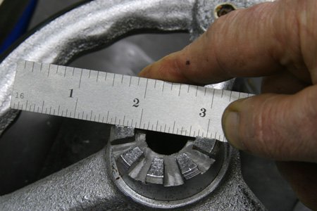
Knee Mill ,crank Handle

dlane

Active User
Registered
Joined
Sep 27, 2014
Messages
3,123
Hi all, the knee elevation handle that came with my mill has some broken cogs on it. I would like to have it rite, I was thinking about making an adapter that I could use a power drill to raise / lower the knee ,but the cogs are tapered ,not sure how to cut tapered cogs ,
Anyone make or buy this handle or adaptor , any suggestions for a good way to raise/ lower knee , don't really want to buy a powerfeed for it.
Thanks for any suggestions.
 
mrpete222 on youtube shows how to do this.
ShopTip#204
 
The taper is pointing towards the center. Not a big deal to machine. Try a search on this sight for making one.
 
Certainly you can purchase such an adapter (I believe one brand is called "Crank Yanker"). My machine came to me without a knee crank (it is a Cincinnati which uses a different face spline than many other mills) - I ended up making a stub with the correct face spline and securing it to a crank from an old Victoria mill. I can post pictures when I get back home.
 
sounds like a great mini project for an up and coming metal worker!
 
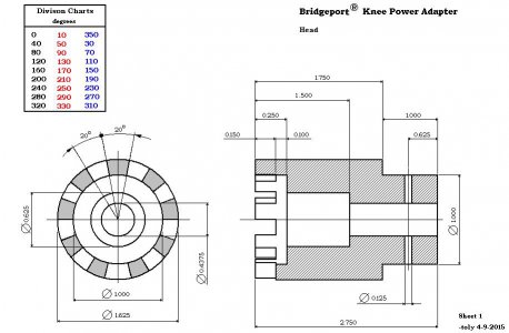
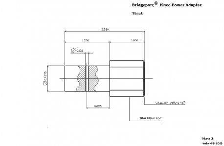
Here are the drawings on the crank adapter. I made one for my mill. If memory serves me correctly, you have to make two series of cuts at different angles. I will try to attach the pfds. If they don't post, PM me and I will email them to you.

bridgeport knee adapter - sheet 1.JPG bridgeport knee adapter - sheet 2.JPG
 
You will find that what appears to be taper is a true radial. if the narrowest point is 3/16, use a 1/8 end mill, (mounted in a super spacer) and (first) cut all the slots, on center, (Second), move off center in Y by .062 and cut all the left sides, then (Three) move off the other way in Y .062 and cut the right sides.
 
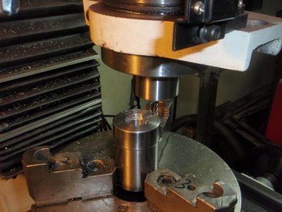
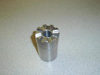
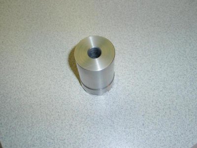
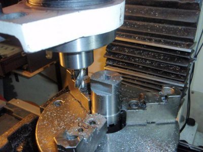
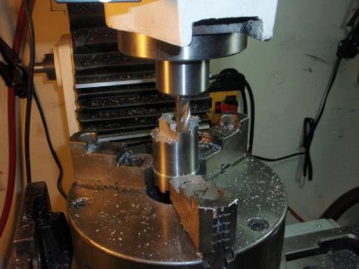
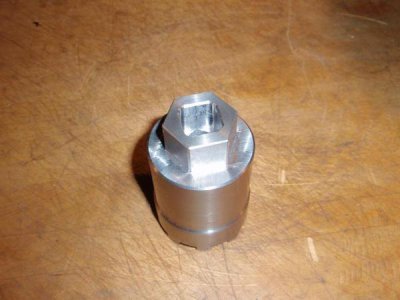
This is how I made one for my Bridgeport clone. I have a length of 1.75" stainless round stock so I used a 2" long piece to machine an adapter for the knee drive splines. It is a 9 spline drive with a 1.675" od. I used a 3/16" end mill and my super spacer on my PM932 mill to machine the spline and a 15/16" hex on the other end as well as a 1/2" square drive hole to use with a drill. I started by drilling a 1/2" hole all the way through and turning the entire length down to 1&5/8". Then I bored it to 5/8" part way to fit onto the knee. Then I milled the splines with 40 degree spacing. I found that if I milled out 4 degrees on each side of each 40 degree interval it gave the correct dimension spline to fit the machine.

P2090659_zpsa8f6aef5.jpg

P2130670_zps986d4502.jpg

P2130672_zps388bd902.jpg

P2130731_zps846d317c.jpg

P2130733_zpscf342d0b.jpg

P2130734_zpsdf96d6e0.jpg
 
Gee, I dunno. I made mine with a total of nine cuts across the entire piece.

At first blush, the nine tooth fitting seemed a bit daunting, but as I stared at it for a while, I realized how easy it would be to machine. I didn't think to take pictures of the job, so the best I can do is a quick description. The key to the operation became apparent when I noticed that the upper and lower edges of opposing teeth were in a direct line that exactly bisected the diameter of the shaft:

handwheel02.jpg

So, all I had to do was center the hand wheel on my rotary table, and cut a straight slot with a 3/16" end mill across both sides of the hub, making sure the edge of my cut was at the center of the hole. Once I'd made nine passes (turning the rotary table 40 degrees for each) I had the job done - and it was a light press fit into the teeth on the knee screw. I haven't even bothered with a set screw, so I can slip the hand wheel off easily and stick on the crank.
 
Back
Top