[How do I?] Late model 10L with two speed motor won't start again after stop. Dead.

itsme_Bernie

Active User
H-M Lifetime Diamond Member
Joined
Jan 11, 2013
Messages
1,821
Hi Hobby Machinist Folks
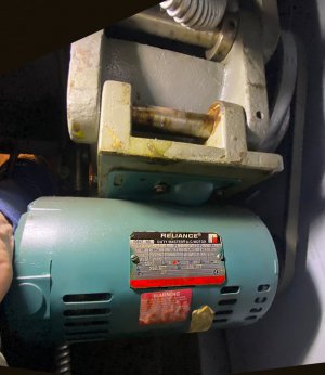
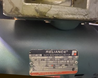
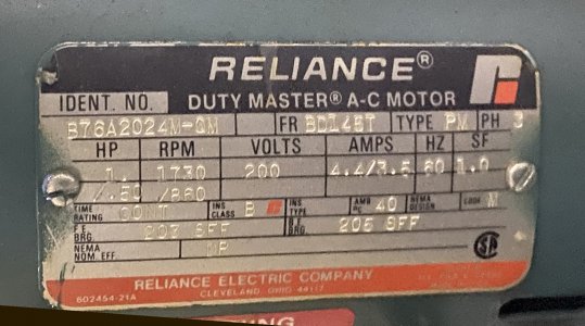
I have a late model South Bend Heavy (10L terms spelled out for searchability) with the "High/Low," 3 phase, two speed motor. In the 1980's, the Reliance two-speed motors were only 1hp in "high", not the 1-1/2hp they were in decades past.
To the problem. I was using the lathe just fine for years. Today, after hitting the Off button and shutting the spindle down after a cut, I hit the button for the next cut, and nothing happened. None of the buttons do anything now. I tried in reverse, forward, High, Low. I disconnected the lathe from the line and reconnected it. I let it sit for a while and tried again. I searched the motor for an overload trip button, or overheat button, and nothing.

I am running this lathe, along with a Bridgeport, on a 5hp PhaseMaster Rotary Converter which are all still working just fine.
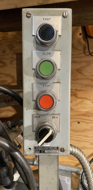
-There is a switch panel on a stalk behind the headstock with three buttons: High, Low, and Stop, and one knob to twist for Forward and Reverse.
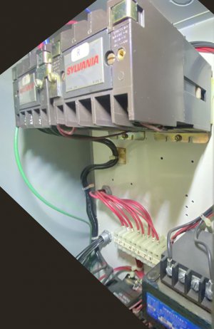
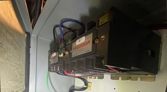
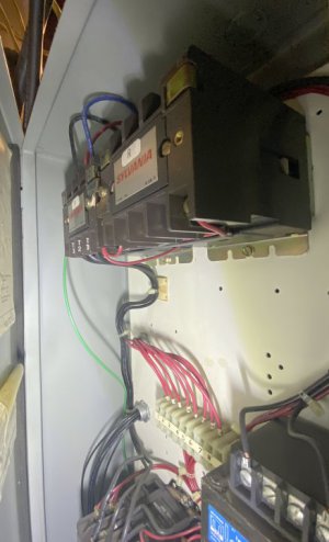
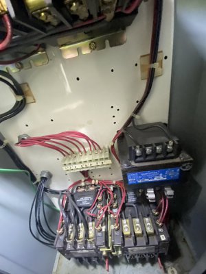
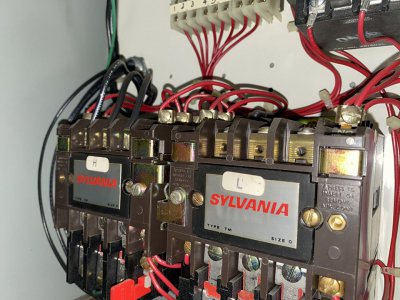
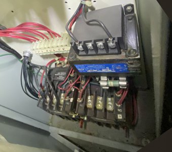
-There is a sizable (OEM South Bend) Sylvania panel hanging on the back of the lathe with what appear to me to be four Sylvania magnetic contactors: two for "Forward" and "Reverse", and two more for "High" and "Low."
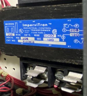
-There is an Impervitran “Industrial Control Transformer” B150M15, which I believe powers the low voltage switches and the relay/contactor secondary windings.

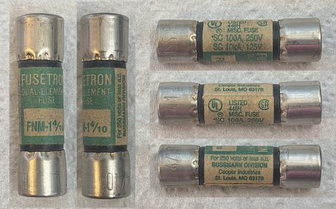
I don't have the easiest access inside this panel right now, but I found only one 10 Amp, 250 volt fuse in the whole panel, on the Impervitran transformer, which I was able to pull, and appears to have continuity.
I understand the basics of magnetic switches, but am not as familiar with troubleshooting them as I am with other motor controls. I can rewire a reversing drum switch (like on a BP or lathe), but would appreciate some clues where to start to get to the bottom of this. I thought I would ask you folks here the best way to identify the problem. Are there spots that are the best to start with the multimeter?

Pics attached in case it helps

Bernie

text for searches:

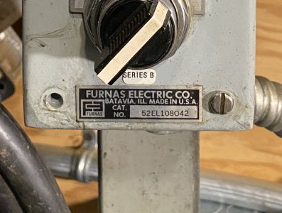
Furnas Switch Stalk 52EL108042 Series B
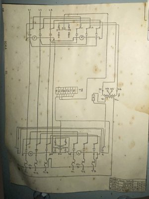
South Bend Wiring Diagram A60-354012
Sylvania T13U030 Contactor Size 0 Type TM 600VAC 18A
Challenger Electrical Controls Lancaster, SC

Impervitran “Industrial Control Transformer” B150M15
FUSE - FNM-1 1 4/10
SC100A 250V
SC10kA 125V

Reliance 1hp 1/2hp Two Speed 3 phase motor
Model B76A2024M-QM
Frame BD145T
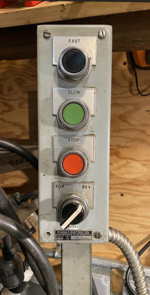


IMG_1761web.jpg
IMG_1733_Coils_web.jpgIMG_1734web.jpgIMG_1735_web.jpgIMG_1735web.jpgIMG_1736_Impervitran_web.jpgIMG_1743web.jpgIMG_1744 Schematic___web.jpgReliance Motor Plate 1_web.jpgReliance Motor Plate 2_web.jpg IMG_1788 Transformer Fuse Pics web.jpg
 
Last edited:
Start by checking voltage on the input to the lathe. Make sure there is power on all three legs. Next I would check voltages at the motor. Do the contactors pull in? If not check the control voltage and circuit . Looking at your first picture the red rectangular plastic part coming out of the over load heaters are resets. There looks like there are two of them. Push them in to reset. That leaves you to trace voltage through the panel part by part. Hopefully one of the electric gurus will explain it better. With any luck it maybe just a reset of the over loads
 
Check (carefully) that you have ac coming out of the transformer, since no voltage there would shut down everything.
I guess next I would remove and check the start button(s) on the bench with a continuity meter or tester.
Suspect the thing that gets the most mechanical use (switches, followed by contactors)
-M
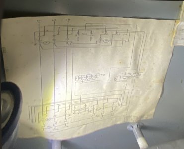
How about a picture of your control panel, and a clearer shot of the system diagram if possible?
 
Thanks Guys... I will try to get a better shot of the wiring diagram.
I had been taking pretty heavy cuts with carbide inserts into 420 stainless steel. It was working very well, I might add. I wonder if I should upgrade the motor itself?
Is this a good time to upgrade from these contactors in some way? Are there quieter contactors? Or ways to quiet them? These ones bang like someone is striking the machine with hammers! hah. I have a VFD in the shop that I could use as well, but I obviously can't while I have these contactors. These questions are not as important as just getting running again, but they are in my head and on this topic so I thought I would throw them out there. What do you guys think of them these days? I know they are used industrially until recently, anyway.

Thank you!
 
Last edited:
Those are good quality, heavy duty contactors so I'm not surprised they are loud when they close. The mounting and enclosure probably magnifies the sound. The vibration may very well be a factor in causing the failure so examine the contactor connections carefully and retighten if necessary any that seem loose (power off of course)
You could use your VFD and throw away all the contactor stuff; you'd have to do some rewiring for the control panel; a bit of a project for the future (but would be much quieter!) plus you would have variable speed instead of just HI and LO
With power off, go around the control box and tug on wires to see if any are loose and pull out of their terminals, look for melted insulation that would indicate a high resistance connection
Thank you Mark

I'm just curious if anything rings with you that this happened in-between cuts.

After thinking about what you said, the only theory I have come up is that some part of the circuit that initially closes the contactor had been compromised WHILE the circuit that KEEPS the contactor closed kept working through the previous successful cut.
Please correct me if I am wrong, but there is one circuit that closes the contactor (initiated by the "FAST" or "SLOW" buttons), one circuit/device in the contactor stays hot and HOLDS the contactor closed until the "Stop" button is hit, which breaks the "keep closed" or "hold-ON" circuit, (otherwise we would have to hold the "ON" button the whole time- "ON" button would be "instant-on"). The OFF button then breaks the "hold-ON" circuit, allowing the contactor to open, breaking the motor circuit. Do I have all that correct?
Since neither the "Fast" nor "Slow" buttons work anymore, maybe a place in the wire/circuit sharing feed to both is loose... Hmmm...
 
Yes you are correct, there is a "latching" circuit that holds the selected contactor closed after the ON button is released, and the two contactors are cross-connected so that it is impossible to have both F and R pull at the same time (would short the power line)
The symptoms do point to some common line that is broken, so that's a clue. Did you verify output from the transformer?
Testing live systems like this is dangerous, I try to minimize the amount of actual hot testing when troubleshooting power stuff.
It should be possible to trace the fault with no power applied, using only continuity tests. I highly recommend that approach.
 
Last edited:
Thank you so much Mark!
I got my machine going again late last evening!
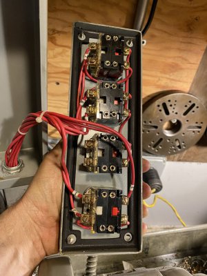
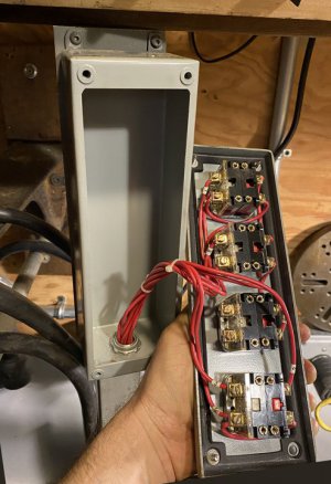
I unplugged the machine again and ended up removing the switch panel from the stalk and just checking the tightness of the wire terminals. I was surprised that they were all only barely tight at all. None were actually loose, but they were all very evenly, "not quite snug." I gave each an extra 1/4 turn to make them actually snug without going ape on them. I will attach pictures for any future searchers on HM.
I went into the back contactor box and just tugged and wriggled wires all over in there, to check that none were loose. I spent extra time checking the "NO" ("Normally Open" ?) and "NC" terminals on the contactors. I also manually closed, and let snap-open the FAST SLOW (marked "H" and "L") contactors a bunch of times to see if they moved easily, and to loosen any debris like spider webs or anything that might have been in there.
That was all it took! I plugged in the machine and it has worked fine. Now I wish I went through more trouble to nail down the exact wire, or even just separated "wiggling the wires" in the contactor box and tightening the switch terminals to see where the issue was, but necessity demanded I just get the machine running. If I run into this again, I will try to take readings to really nail it down.


Furnas Switch Stalk 52EL108042 Series B
South Bend Wiring Diagram A60-354012
Sylvania T13U030 Contactor Size 0 Type TM 600VAC 18A
Challenger Electrical Controls Lancaster, SC

Impervitran “Industrial Control Transformer” B150M15
FUSE - FNM-1 1 4/10
SC100A 250V
SC10kA 125V

Reliance 1hp 1/2hp Two Speed 3 phase motor
Model B76A2024M-QM
Frame BD145T


 IMG_1795 Schem web.jpg IMG_1794 Sylvania Fast Slow High Low Contactors web.jpg

 Reliance Motor Plate CLOSE web.jpg

 Furnas Switch Stalk Plate 52EL108042 Series B web.jpg IMG_1761 Furnas F S Switch Stalk web.jpg IMG_1797  IMG_1805 Inside Furnas Switch Stalk 2 web.jpg IMG_1805 Inside Furnas Switch Stalk Web_.jpg
 
Start by checking voltage on the input to the lathe. Make sure there is power on all three legs. Next I would check voltages at the motor. Do the contactors pull in? If not check the control voltage and circuit . Looking at your first picture the red rectangular plastic part coming out of the over load heaters are resets. There looks like there are two of them. Push them in to reset. That leaves you to trace voltage through the panel part by part. Hopefully one of the electric gurus will explain it better. With any luck it maybe just a reset of the over loads
Thanks Nutfarmer

I did end up flipping the contactor open and closed a few times (power disconnected) by those red levers. They my be resets, but these seem to stick out in the position in my pictures normally. Maybe they stick out further if popped? It turns out I did not have them pop, but I believe I had a loose wire on one of the switch terminals, but my wiggling the wires in the contactors, or flipping them manually a few times may also have done something. They are also only on the set at the bottom of the contactor cabinet- the FAST and SLOW settings (marked "H" and "L", "High" and "Low").
I'll post if there are any more updates!

Bernie
 
Good deal! It probably won't happen again, but yes, it's better to wiggle/tighten a few wires at a time to try to narrow it down. Next time :)
BTW do you still work on clocks?
 
Last edited:
Back
Top