Lathe cross threading

The spindle and the lead screw are LOCKED into proportion by gears. The lead screw and dial are LOCKED in a 1:1 relationship. All that matters is the engagement of the half nuts must occur at the same carriage position and the same dial position. You see, the other relationships are mechanically inseperable, locked in and fixed. The point is to select the ORIGIN, unitless and dimensionless, where all initial conditions (dial, carriage position) are initiated. The resulting movement is explicitly dependent on initial conditions. Replicate the initial conditions, replicate the movement.
Sure. Repeat the spindle turns in reverse and get back to the same initial conditions (origin). You’re ignoring the fact that you don’t have to return to that origin to get the thread dial to align again. It repeats periodically so you can get there by continuing forward. Unless the change gears keep that period tied to the period of the spindle so that the spindle is a *harmonic* of the thread dial, it may not align every period of the of the thread dial. There are change gear ratios that don’t keep the thread dial aligned with the spindle.

Think about clock hand alignment if there was a broken clock who’s minute hand had a period of 23 minutes. Even if it starts correctly with both hands vertical at midnight, they won’t both be vertical 24 hours later. They are still locked in a ratio, just not one that has a common period, at least not a useful one.
 
Last edited:
nope, you can't.

What you can do is disengage, stop, reverse and reengage when your number comes back at you.. So you are really at the same spot.
But no, with an imperial lead screw, you cannot leave your number even for one rotation. you must be on the same tick and that needs to be the same spot on the lead screw, no rotation.. should I say it a third time.??
This is what I have had to do. Does not work, just to come back to the same thread dial number.
 
Interesting responses, guys. I think I've come to understand that Radal and RJ are right about false harmonics occurring. I also still think my bent is reasonable, if I do only one thing differently- put a sharpie mark on the chuck to index from. Cut a pass, kill the power, move the carriage back (a hard stop seems useful), verify the idex mark on the chuck is correct, and repeat. Where the index isn't correct, roll the chuck by hand until it is, turning the feed screw along with it. Now you've got accountability of the spindle and the leadscrew dial.

If I have to roll the chuck by hand 127 times, then this would be a --itty method. I'll try it next time I get the chance.
 
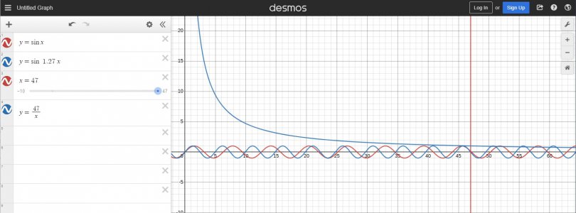
With a 127:100 gear as an example, the origin only repeats after 47 turns. There are false harmonics at two nodes where the half nuts and lead thread line up close enough to engage. So I concede that it would probably cause less trouble to leave half nuts engaged instead of trying to fook with it.

Screenshot 2023-07-14 125544.jpg
 
I'd suppose if one had encoders on the lead screw, carriage position, and spindle angle one should be able to get back to the equivalent point? Assuming one knows all the gear ratios.

Is this a case where the all of the above could be expressed in matrix math? If that is the case, (since we know that matrix multiplication is not commutative,) one would have to back track in the correct order, else, "you can't get there from here". Not practical on a geared system, but on an electronic one, one could wait for some magic point and electronically create the sync.

In the graph above, the repetition at 47 is not the same sign, it is the opposite slope. Don't know that it matters, but it isn't a true common period.
 
With a 127:100 gear as an example, the origin only repeats after 47 turns. There are false harmonics at two nodes where the half nuts and lead thread line up close enough to engage. So I concede that it would probably cause less trouble to leave half nuts engaged instead of trying to fook with it.

View attachment 453921
Wow! I'm not smart enough to do something like your graph!
 
I can't believe there is any debate on this. lol
 
I'd suppose if one had encoders on the lead screw, carriage position, and spindle angle one should be able to get back to the equivalent point? Assuming one knows all the gear ratios.

Is this a case where the all of the above could be expressed in matrix math? If that is the case, (since we know that matrix multiplication is not commutative,) one would have to back track in the correct order, else, "you can't get there from here". Not practical on a geared system, but on an electronic one, one could wait for some magic point and electronically create the sync.

In the graph above, the repetition at 47 is not the same sign, it is the opposite slope. Don't know that it matters, but it isn't a true common period.
I think with an ELS and rotary encoders (using missing tooth pattern encoding or similar to facilitate a live sync), it would be possible to write a program to zero out, lock rate, and start count. It would be like calling up a G code, setting the rate and position, and pressing go on each pass.

The sign at 47 in my example is not important, anywhere where spindle and lead meet at 0 is a node given a fixed carriage start point. Close but not quite alignments (false nodes) will result in a cut displaced longitudinally, but would probably still feel like a natural fit on the closing half nuts- a situation we must avoid.

Can't believe there's a debate? Well, there were two ways to consider it, is it possible and is it practicable? Not the same question. I got hung up on whether it was possible, and I say yes- under certain circumstances, it would work out to unclamp, index, and restart. Under other conditions, like having large prime numerators for metric from inch, the number of useful engagement points shrinks and false nodes appear making it impracticable (that means not very useful in practice, as in the real world that we operate in).
 
The way I look at this- The leadscrew on my lathe (and most) is a single start thread. EVERY time you drop the half nuts, they're in the same thread. You're not looking for a particular thread. That gear and dial are doing math (mechanically, like an old adding machine), to tell you when you've been the correct amount of revolutions to to have the chuck and the leadscrew come back to the same exact relationship as when you first started. Or some acceptable fraction thereof, depending on the thread pitch.

If you add the 127 tooth gear, you have fundamentally changed the geared relationship(s) that the threading dial depends on, by adding a large, prime number into the mix. A prime number that is very incomatible with the mechanical counter, who's mechanical "software" still thinks it's counting four inches per revolution, but now you're "inputting" millimeters.... You'd have to have a minimum 127 leadscrew revolutions, or 127 teeth on your thread dial gear, to get one single line on your dial, to achieve -any- useful realignment of the chuck and the leadscrew, and I think (I'd have to work on it, it's not lazy math.....), I think it would probably need a geometric multiple of 127 teeth. And still have to wait for your exact number to come around every time. Even at 127, that's gonna be a big honkin' thread dial.
 
Back
Top