[How-To] Lathe tool bit modeling

WobblyHand

H-M Supporter - Diamond Member
H-M Lifetime Diamond Member
Joined
Dec 18, 2019
Messages
6,448
I'm thinking about modeling a lathe tool bit. I need a model of a lathe tool to design a fixture to hold the bit at the correct angle to hone it. Having a devil of a time understanding how to cut away the tool bit properly. I'd like to position a datum plane in space, so I can position a pocket properly. I know that doing the rotations in space is not commutative, so the order matters. I think I should do the rotations first then the translations.

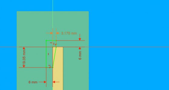
I am trying to cut the tool along the diagonal line, but the datum plane should be rotated about that line by -10 degrees. Then I could do a pocket which has the proper relief.
examplecut.jpg
If someone could give me a couple of tips on this, it would be helpful. The line is 9.46 degrees from vertical. I'd like the datum plane to intersect that entire line, and be rotated about the line's axis so that the left side is -10 degrees. Darn, I can't even express this correctly! It's easier to grind the tool than to make a model.
 
I'm not sure how freecad works, but using Alibre I did it by creating planes at an angle to the model, then sketching and extruding profiles from the angled planes. In a couple places I used a partial revolve cut, using a model edge as the axis of rotation.


Freecad very likely allows similar operations. Either the 3 point method or rotation of plane around an axis/edge method of creating planes would likely be easiest in this situation, if freecad has that ability.

Here is a video I made awhile back for Alibre users. It covers various methods of creating work planes. Freecad likely has some similar tools for doing this.

In the past 2 decades I've used Inventor, Fusion, SOLIDWORKS and Alibre, and all have very similar methods of creating planes.

 
Last edited:
I'm not sure how freecad works, but using Alibre I did it by creating planes at an angle to the model, then sketching and extruding profiles from the angled planes. In a couple places I used a partial revolve cut, using a model edge as the axis of rotation.


Freecad very likely allows similar operations. Either the 3 point method or rotation of plane around an axis/edge method of creating planes would likely be easiest in this situation, if freecad has that ability.

Here is a video I made awhile back for Alibre users. It covers various methods of creating work planes. Freecad likely has some similar tools for doing this.

In the past 2 decades I've used Inventor, Fusion, SOLIDWORKS and Alibre, and all have very similar methods of creating planes.

I will watch this.

Took me a while to figure out how to think about it. Knew it was associated with a local coordinate plane rotated in space. Just haven't found a way of doing it, primarily due to my newness in learning the tool. I can do the first line rotation on a plane easily, but the second plane rotation about that rotated line is what I'm having a problem with. Sure it is operator error, or at least I really hope so! Once I get the plane sorted out, everything should be relatively straightforward. Thanks for giving me some keywords that I can use for searching the FreeCAD docs. Had no idea what to search for!
 
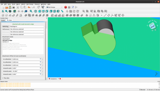
@Ken226 very helpful video! I have learned a lot by just watching! I'm about 1/2 way through now. FreeCAD doesn't seem to be as straightforward as Alibre, but just seeing some of the thought process helps a lot. Just got a plane in the correct place, using part of your example. Will play some more with it, but some progress has been made! Thanks! Still have a ways to go, since the line I want isn't normal to the other edges, but hope to figure it out. Need to find a tutorial on all the different attachment modes.
plane_on_edge.jpg
Screenshot from 2022-04-25 09-32-56.png
 
I have not learned anything outside of Solidworks since 2004, when I realized SW works the way that I think and Autodesk does not. There are several ways to skin this cat as far as relating your references and what not, but at the end of the day we are creating clipping planes to grind faces onto a solid primitive.

If I had a lathe bit that was 3/8 square, I would sketch the bit as such. Then I would define a plane on the top and bottom of the tool, and on those planes I would draw the ground faces with no relief on top and relief included on bottom. Then I would create planes from those lines as references for subtraction from the model. From there, the plane geometry can be tweaked to specific angles using dimensions as needed.
Thanks for the ideas. It's a matter of learning the mechanics of the SW tools. New stuff for me, so it's a bit of a stretch. Each new thing I have to draw involves learning yet another facet of the tool. My approach is similar to what you have stated, but am having a little trouble with how do I get FreeCAD to do that. Everyone's help gives me yet another keyword that I can eventually find out how to do it. A lot of the tutorials cover trivial cases. This isn't trivial, or at least I don't know how to reduce it to the trivial case. Been struggling with how to define the plane in a way that FreeCAD understands. If I plod away at it, I'll eventually get it. It would be nice to find a similar example in a FreeCAD video, but haven't found anything like to this. For instance, a video on using 3 points to define the plane. Shoot, can't remember to calculate that 3rd point by hand - my 3d geometry is rusty.
 
Thanks for the ideas. It's a matter of learning the mechanics of the SW tools. New stuff for me, so it's a bit of a stretch. Each new thing I have to draw involves learning yet another facet of the tool. My approach is similar to what you have stated, but am having a little trouble with how do I get FreeCAD to do that. Everyone's help gives me yet another keyword that I can eventually find out how to do it. A lot of the tutorials cover trivial cases. This isn't trivial, or at least I don't know how to reduce it to the trivial case. Been struggling with how to define the plane in a way that FreeCAD understands. If I plod away at it, I'll eventually get it. It would be nice to find a similar example in a FreeCAD video, but haven't found anything like to this. For instance, a video on using 3 points to define the plane. Shoot, can't remember to calculate that 3rd point by hand - my 3d geometry is rusty.

I did a quick n dirty screen capture showing some of the strategies i used for modeling a lathe tool.

It wont be perfect, considering your using an entirely different CAD program, but perhaps itll give you some ideas.

 
I did a quick n dirty screen capture showing some of the strategies i used for modeling a lathe tool.

It wont be perfect, considering your using an entirely different CAD program, but perhaps itll give you some ideas.

Thank you very much. Will spend some quality time with this! Going cross SW packages definitely makes this tougher. Appreciate your help a lot.

I don't mean this as a diss to FreeCAD, but it has a European mindset to it. Can't quite describe it, but some of the thought process, or how one does things are foreign. So some of the SW approaches are different than I'd take. It's not bad or anything, but it is different, and it takes some getting used to.
 
I did a quick n dirty screen capture showing some of the strategies i used for modeling a lathe tool.

It wont be perfect, considering your using an entirely different CAD program, but perhaps itll give you some ideas.

Outstanding! Just watched this! Hope there's an equivalent in FreeCAD. I'll find out soon.
 
Back
Top