Lathe wiring help needed.

Ski, now that John and I have you completely confused, I'll try to clear that up.

First, you don't NEED the mag starter in the circuit at all, everything you want to do can be done with the drum switch. FOR/OFF/REV

Since you have the mag starter, you MAY use it to add a little safety to the system, by adding an E-Stop button.

If you are going to add an E-Stop button, then you may as well add a Start button while you're at it.

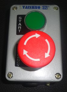
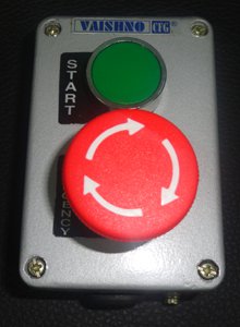
Something like this is what I have in mind.

push-button-station1.jpg

The mag starter is already wired up to accept this kind of a switch system, there are 3 wires to connect.

You don't have to buy the entire assembly as you see it. Your local hardware store will have a suitable box. The switches are about $12 each. You could do a little scrounging and maybe come up with one from an old piece of industrial equipment.

Let us know what way you want to go, and we'll help you with the wiring.


I agree with your suggestion for the remote start & safety. I have sent a private message offering a free used start/stop NEMA enclosure to my fellow "Badger" member.
push-button-station1.jpg
 
I like the idea of an emergency stop. How would this work in conjunction with the mag switch? Use green start switch to start machine and then use Drum switch for ON/Off in either forward or reverse? If power drops to building/machine the mag switch drops out and would have to be reset? If Emergency stop is used ,reset it and go? Also what specs as far as the switch are important for this motor, as far as amps/volts ? You Gents are not confusing me ,you are educating me and I am grateful for your help. Ski
 
This is the standard 3 wire motor start circuit. The E-Stop is what's known as a Maintained switch. Once pushed, it locks in the OFF position and drops out the mag starter. You have to twist to unlock, then you have to push the Start button to energize the motor starter again. In order to use this, you would remove the wires from the existing Start/Stop buttons on the mag starter, and wire this in it's place.

All standard industrial push buttons are rated for this use. You are not switching the motor with the push buttons, only the coil in the contactor. The contactor is switching the motor current.

EDIT: There is also a way to wire this to give you a Jog function when the E-Stop is pushed in.
 
I like the idea of an emergency stop. How would this work in conjunction with the mag switch? Use green start switch to start machine and then use Drum switch for ON/Off in either forward or reverse? If power drops to building/machine the mag switch drops out and would have to be reset? If Emergency stop is used ,reset it and go? Also what specs as far as the switch are important for this motor, as far as amps/volts ? You Gents are not confusing me ,you are educating me and I am grateful for your help. Ski

The start switch & the remote start switch are wired in parallel & the stop switch & remote E-stop switch are wired in series. The motor start contactor remains started after initiating & only disconnects if the stop switch or remote E-stop switch are pressed. The FWD/REV switch connects power to the motor only if the motor starter is activated. The advantage of a remote start & E-stop station is easy machine control from the same location as the reversing switch.
 
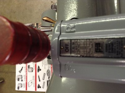
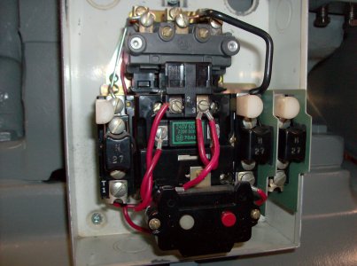
Ok Guys, I will wait tp post anything furter until I recieve the start/emergency switch from Uncle Harry and then get it mounted next to the Drum switch. I put a pic in of the switch as it is now. I have to scounge some wire and a few other minor things as well. Thanks to everyone helping. Ski

image.jpg
 
Hi,

As long as I am sending the switch box, I can include some 16 AWG MTW stranded individual wire. I have lots of red for 120 "hot" control, White for neutral & probably some 16 AWG green for grounding purposes. If the coil is rated 220 VAC black should be used. I'd hate to waste all that air space in a USPS box so I'll 'scrounge' some wire as packing material. I'm assuming that your motor is wired for 220. I'd also suggest that your electrician provide a neutral for the control & other 120 VAC accessories like a light etc.

For added confusion, the nice feature of the E-stop is that if you E-stop the lathe safety relay it remains safe should a Grand child fool around with the push buttons at the back of the lathe; it wont start because of the detent in the E-stop.
 
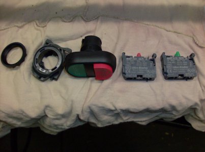
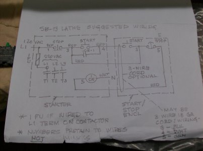
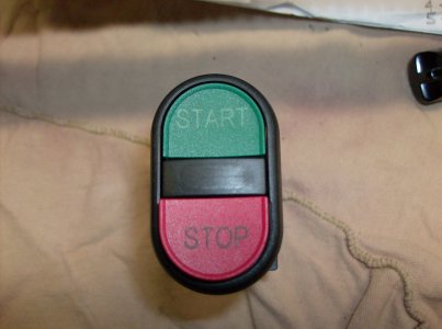
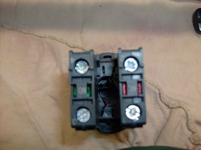
Hello again ,I received a switch and some wire and other parts from Uncle Harry. The switch has several parts but I got that figured out. The stop is a NC and Start is a NO. Seems it is rated for 10amp. If this will work ,all I will need to do is source a box for it. I am also posting a Wiring diagram from Uncle Harry that shows how to use these switches. It seems I will have to combine it with Jims. I want to get Jims input here as well since both Jim and uncle Harry have contributed. I believe the upper part of Uncle Harrys schematic applies since I do not have a neutral. Also unsure of what the 120vac coming in and what 1FU means? I added a close up of the magnetic switch as well. Ski

13 South Bend Electrical 005.JPG 13 South Bend Electrical 007.JPG 13 South Bend Electrical 008.JPG 13 South Bend Electrical 009 - Copy.JPG 13 South Bend Electrical 011.JPG
 
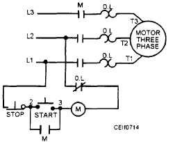
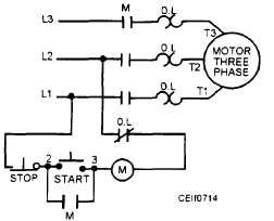
Here is the best diagram I could find

Ignore L3 and T3 since you are operating on single phase, T1 and T2 will connect to the reversing switch as L1 and L2

You just disconnect the wires going to the existing Start/Stop switch, and connect the new remote switch in their place.
M is the existing contactor, the M in the circle is the coil in the contactor. It is already connected to L2 through the O/L and the coil (M).
The M below the start switch is the auxiliary contact, labeled 2 and 3 on the contactor. 3 is already connected to one side of the coil.


14027_194_2.jpg

Wiring like this will operate the contactor. The O/L terminals are already connected to the output terminals.

FU1 = Fuse 1.

I'll be around if you need more info.

14027_194_2.jpg
 
Back
Top