Learned something today

WobblyHand

H-M Supporter - Diamond Member
H-M Lifetime Diamond Member
Joined
Dec 18, 2019
Messages
6,464
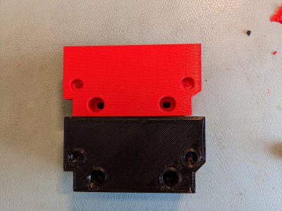
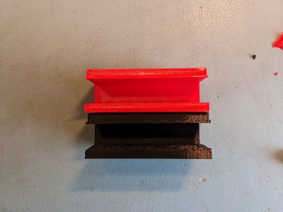
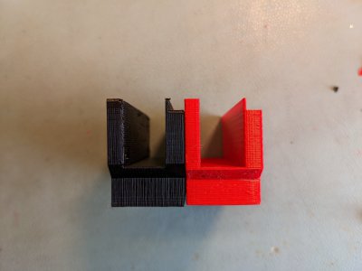
I designed a read head bracket for my X DRO scale. Gone through a few iterations to refine the design. I had been printing them with the U pointing up, but with horizontal through holes for the fasteners. In draft mode, this resulted in some not very nice looking screw holes and counter bores. They were kind of flattened on the top and bottom edges. Reducing layer height helped some, but still not very good. I used a drill and end mill to open up the holes. There were supports inside the holes, which I had to hammer out using a punch.

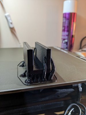
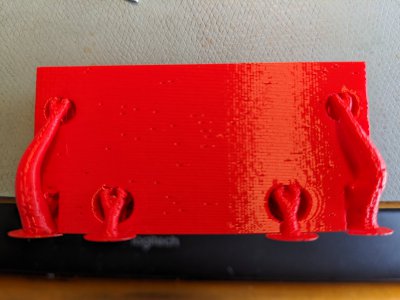
I then thought, what if I print the part laying on its side? Then the holes would be in the horizontal plane and would print better. The U would then be unsupported. But then I remembered seeing @Ken226 using organic supports on overhangs. So I gave it a try. Came out surprisingly well.
PXL_20230330_153639395.jpgPXL_20230331_182906681.jpgPXL_20230331_182927292.jpgPXL_20230331_182943561.jpg
So don't be afraid to have an overhang. That thin little section is 1mm in the black, and about 0.8-0.9mm for the red, due to the change in layer orientation. My CAD design has it being 1mm thick.
 
Yea, the organic supports are great. I missed them when I switched and started using PrusaSlicer and Cura. They were one of my favorite tools in Flashprint. Flashprint (Flashforge's proprietary slicer), called them "tree supports"

When a part is intended to be 3d printed, I like to approach the design with that in mind, right from the beginning.

There are lots of little tricks that a designer can use when a part is meant to be 3d printed that make for better results.

A couple examples:

When desiging holes that will be larger than 1/4" in diameter, i create the sketch for the hole with a bit of teardrop, like this:
1680289760776.png


Which results in a hole like this:

1680289826077.png


The end result is that the 3d printer no longer has any overhang exceeding 45*, and once it gets to the top layer, its a short, simple bridge. So, there is minmal, if any, sagging in the roof of the hole. Here is a sequence of layers from the slicer, of the same hole:

So, here is clear that the overhang is an easy 45*, no issue at all for most any 3d printer.
1680290067537.png


and when you get to the roof, the 3d printer will have no trouble with such a short bridge on the first roof layer:

1680290135735.png
 
Not sure I follow completely. How does a cut end up being a bridge? By a cut, you mean remove the material? And you are mirroring it across the hole axis? Your command of CAD is far beyond mine, so I'm trying to figure out what you are doing.
 
Deleted in lieu of the video in post 13. That should explain more clearly than a wall of text and a dozen pics.
 
Last edited:
@WobblyHand ,

Sorry I must be a little thick myself.......

I believe the problem was that the red one was printed U-up, but the horizontal thru-holes were odd shaped. right?

So then from the layers, the black one was printed on it's side.
What do you mean by "organic supports"?
Just the ones added automagically by the slicer or something else?

Thanks
Brian
 
deleted in lieu of the video in post# 13
 
Last edited:
@WobblyHand ,

Sorry I must be a little thick myself.......

I believe the problem was that the red one was printed U-up, but the horizontal thru-holes were odd shaped. right?

So then from the layers, the black one was printed on it's side.
What do you mean by "organic supports"?
Just the ones added automagically by the slicer or something else?

Thanks
Brian
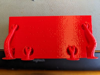
Organic supports look like trees, sort of. They are in some slicers. I am using PrusaSlicer 2.6.0 alpha4, which has organic supports. The standard release of PrusaSlicer 2.5.2 does not have these yet. Here is a not quite focused picture of organic supports on the red piece. The flat pads on the bottom is the print bed location. U was printed up.

Allegedly the organic supports use less material than normal supports. I use them because of that, and they do look pretty neat!
PXL_20230330_153639395.jpg
Slightly better picture of an earlier prototype print, still on the print bed, although in black PETG.
PXL_20230329_235424078.jpg
 
So now, the same part but with the first staggered bridging cut. In this pic, the 0.2mm deep cut is highlighted in blue.

View attachment 443105


This cut fools the slicer into connecting the strands at each end. like a bridge. Because of that extrude cut, it goes back and forth for that layer, bulding a bridge that straddles the center of the hole. Since its connected at both ends, its a "bridge", and nothing falls down into the hole.

View attachment 443113

With that last one, just one bridging cut only bridges that first layer. The secoond layer going up would have some issues

You can see, its still trying to print some circular rings in mid-air

View attachment 443116


So, now, I added a second bridging cut, inside the first, also 0.2mm deep

View attachment 443114


As a result, on the next layer up youll get

View attachment 443120

then on the next layer

View attachment 443121


then the next

View attachment 443122


In this last pic, you can see that the unsupported curved strands (dark blue), are very short and connected at the ends. So, they are also "bridged"

Whereas in the first example, without those staggered bridging cuts, the dark blue strands were fully circlular, with no connections (yellow).
I think what I was confused about was where this was done. Is this done in the slicer? If so, how do you access this?
 
Back
Top