LED spindle light

Two of my posts were lost during this website change over / turmoil. I'll wait a little longer and attempt to recreate them.
 
Seems like those posts are gone... Ok, let's try again.
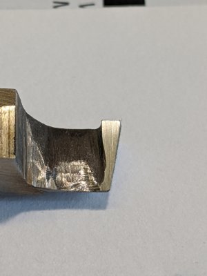
Reground the tool, by touching the bit to the belt sander. Didn't even have the tool hit the platen, just the belt for a brief second. It was enough to remove nearly all of the flat part. There only was a tiny spot on the right hand side that didn't get cut. Cutting edge has 14 degree relief. Honed with 325, 600, 1200 grit diamond cards. Flattened the corner along the cutting edge, so it wouldn't break off.
IMG_20200419_113132.jpg
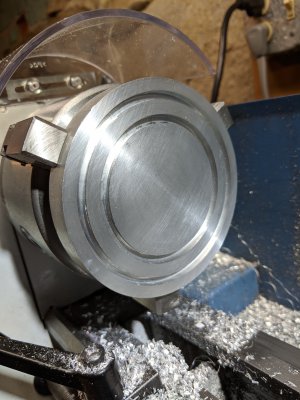
Used the parting tool to machine the grooves on the other side. Just flipped the disk over. Then used the super improved tool shown above to machine in the retaining lip. Here they are. Tool cut well. Workpiece remained cool.
IMG_20200419_144031.jpg
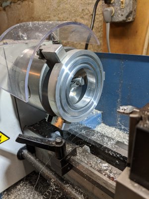
Then I bored out the center. Only minor casualty was the tips broke off the cheapo T8 tool when I tightened an aluminum insert in the boring bar. Fixed that later by touching the T8 tip to the belt sander. Also ordered a proper T8 screwdriver.
IMG_20200419_164640.jpg
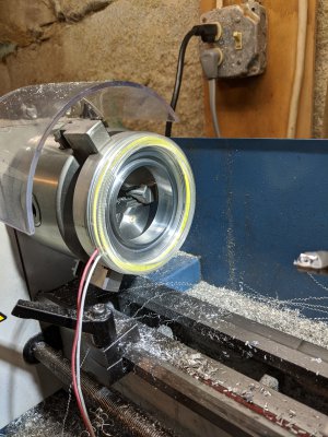
Next we did a fit check. First the outer ring, and then the inner.
IMG_20200419_164755.jpgIMG_20200419_164853.jpg
Hooray, they fit! Inner is a bit snugger than the outer, but it's good enough! I removed the part from the chuck and did a fit check on the drill press. Spindle passes through, but the workpiece needs a chamfer to fit a little better. Back in the chuck. While I was at it, I machined down the mis-machined slot (affectionately known as the practice slot ), and then put in the chamfer. Final thickness of the ring is 3/8". Yeah, I meant that, really, I did!

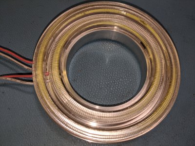
Then it was time to add some mouse holes in the LED rings for the wires to pass through. In the pictures above, the plastic edge was pressing on the wire insulation. Long term, that's not good. Used the edge of a rectangular needle file to cut some tiny slots for the wires to pass through. I then placed some kapton tape over the solder joints on the back of the LEDs to prevent shorting out. Assembled everything to get an idea of my progress.
IMG_20200419_195219.jpg
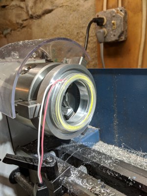
Hmm, that's not too bad. Couldn't stand it any longer, needed to light it up. Wired to a small LED power supply and there was light!
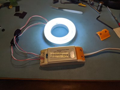
IMG_20200419_195049.jpg
Woohoo!

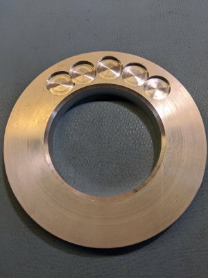
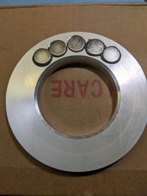
What's left to do? Need to counterbore some holes in the backside of the ring. The holes are for N52 magnets. Only 5 12mm diameter magnets have direct contact with the underside of the drill press. These magnets are pretty strong, so I think it will work. There is a 0.030" gap between the back of the workpiece and the drill press. The magnets are 0.105" thick. So the counterbore needs to be about 0.075". I'll epoxy them in place. Guess I should counterbore a tiny bit more to allow for the epoxy. Now the wait begins - don't have the tooling. Tools on order, will have them and other toys(tools) within the week.

While I'm waiting, I'll figure out how to hide the power supply inside the drill press and wire in a switch. I hope to tap off power from inside the unit to power the lights. That way I won't consume another plug in my constrained shop. Considering that these LED lights consume less than 10W, I think it's pretty safe to do so.

Hopefully this post won't get eaten up by the great IP switchover...
 
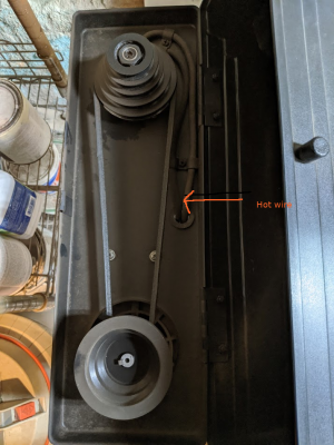
After cleaning out the remnants of a mouse nest in the drill press, I traced out the wiring. It's pretty easy to determine which is the unswitched (always hot) wire. I will tap power from the hot wire. That way, I can power the light without having the motor running. The live wire is the one on the outside.

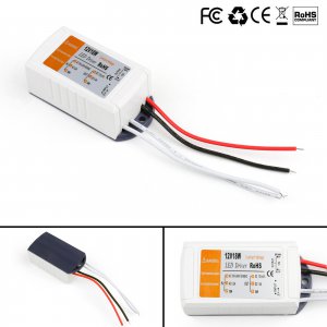
My LED supply is a little bit big for the available space, and it isn't sealed. I don't like the idea of belt dust getting into the electronics, nor the belt slapping the case. The approximate location of the power supply is below the grommet and along the right side. So off to eBay to find a sealed and slightly smaller unit that I can wire inside. Found something that should work. It's 2.9"x1.5"x1.1". Unfortunately it's not sealed. A little RTV can fix that. The sealed units seem to be significantly longer and would be difficult to wire in.
drillpress.pngH003-069-Set.jpg
 
Power supply still not in. Few more days, I hope.

While I was waiting, attempted to counterbore some holes for the magnets. They are done, but not going to win any medals. Using an end mill on a drill press on an el cheapo xy table was quite the experience. Yeah, somehow, some day, there will be a mill in my shop. No two ways about it. Oh the chatter! The non-repeatability! Bore depths not the same, but using the drill stop. Lucky to have made it through the experience. This is what I have so far. Not happy about it, but it's still ok.
IMG_20200427_172508.jpg
I have to epoxy down the magnets and clamp them so they don't jump to each other. Hopefully won't glue my clamp to the piece. Going to use a piece of steel so the magnets will stay in place. Alternating the polarity of the magnets yields a lot of holding power, much more than non-alternating.

These magnets are powerful. I put in one magnet at the far left, and one in the middle. It stayed that way for about 30 seconds, then both magnets jumped in air about 4 inches, stuck to each other, and fell as one unit. I was really startled by it!
 
Non-action shot clamped magnets in a vise. Steel keeper plate holding the magnets in position. Spindle ring and magnets cleaned with isopropyl alcohol. Magnets are JB Welded and clamped. Hope it holds. 24 hours later, we will find out.
IMG_20200428_152823.jpg
 
Last edited:
24 hours later, the moment of truth, err, oh dear, the keeper doesn't want to come off... Managed to twist it off. A tiny bit of epoxy was glued to the keeper. So far, so good. The 5 magnets have pretty good holding power. Still no power supply, but at least there is some progress.:)
IMG_20200429_220116.jpg
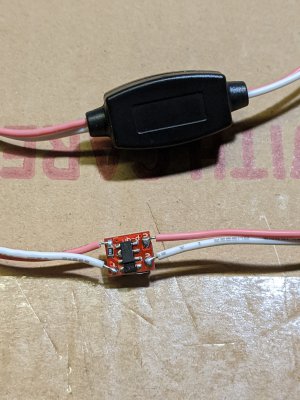
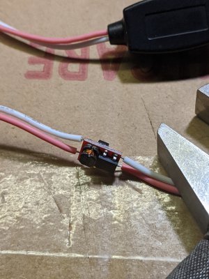
Well, the curiosity got the better of me. I was wondering what was inside these little black modules clamped on the wires.
IMG_20200429_222010.jpgIMG_20200429_222118.jpg
I wasn't expecting that! I thought they just were kludgy crimps. Good thing I didn't cut them off. Look like power supply components. It seems there are two IC's and some kind of transformer, or inductor. The circuit probably regulates the current to the LEDs. Back go the covers. Well, so much for neatening up the unsightly bump!
 
Oh, to be mill-less ... :bawling:

This is a very sad state for a hobby guy to be in. @DavidR8 was that way and didn't even have room in his shop for one but he found a way so you must follow his example and cure this sorry condition of yours. I won't comment on the condition of your man parts; we all know what not having a mill does to them. Instead, I will just say that we will keep you in our thoughts as we shake our heads in sympathy ...
 
@mikey, Ok, maybe I earned your comment. Nonetheless, financial considerations preclude a mill purchase. Being unemployed for an extended period makes one painfully aware of these niggling details. Some day there will be a mill, but not immediately. In the meantime, I'll just do the best I can. Like @DavidR8, there's no room for a mill in my shop. It didn't stop him, and it won't stop me, but it will take a while to come to fruition. If I had a crystal ball, (who wouldn't want one now?) I'd say it would be at least 6 months before I could even think about a mill. Of course, if a mill showed up in my lap, I'd be hard pressed to say no.
 
Be careful! @mikey loves to spend your money and you'll have a Bridgeport in your garage before you know it! On the up side, he doesn't waste your money and recommends good stuff, but good and cheap rarely go together.
 
Wouldn't that be great! I'd love a Bridgeport. Anyone care to gift me one? ;)
Having recommendations on 1) how to size a mill, 2) what to look out for or avoid would be helpful.

You know, start the researching early, so I could get something that would meet my needs. @DavidR8 has lots of threads, maybe he has something already documented.
 
Back
Top