Low profile centering tool

homebrewed

H-M Supporter - Gold Member
H-M Supporter Gold Member
Joined
Jul 28, 2017
Messages
2,379
This is my version of a low-profile centering tool, prompted by a recent discussion on the subject:
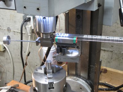
Finished.JPG

It's based on a linear slide I bought on ebay. The slide is adjusted using 4-40 all thread. I made a simple anti-backlash setup with a threaded plate, a little spring and an anti-rotation screw. The other end of the all-thread drives the slider. That side has two miniature thrust bearings to eliminate backlash.

The tool is held by a 3/4" R8 collet, which, in turn, provides the greatest amount of Z motion. It will be a little unhandy to use because I rarely use end mills that large -- so I probably will make a piece that will fit my most-commonly used end mill collet size.
 
Interesting! Can you point me to the recent discussion? I'm curious about the advantages compared to just using an indicol.
 
Interesting! Can you point me to the recent discussion? I'm curious about the advantages compared to just using an indicol.
Unfortunately I've been unable to find that discussion, not sure why. Maybe someone reading this will chime in.

I considered something like an indicol, but I had most of the components -- linear slide excepted -- on hand. The slide cost me about $15. And then there was the "fun" component :p.

I had originally planned on implementing a differential screw for very fine adjustments but so far that looks like overkill. The DTI shown in my photo is a .0005"/division model and it was very easy to adjust using the 40TPI screw. I have a .0001" DTI but so far haven't found it necessary to use it for this kind of thing....yet.... (and I'm sort of hoping, never!).
I did a differential screw adjuster for my mini-lathe tail stock. That was fun getting it all to work. Hardest part was figuring out how to get sufficient coarse adjustment range, the differential screw itself was pretty easy. It was a M6x1 + M5x0.8 screw. Coarse adjust was 1mm, differential was 0.2mm/turn (0.0079"/turn).
 
I have been using a coaxial indicator, each time thinking how annoying it was to get the right length arm for the diameter of the item so to not exceed the limited range for an initial off center part. Recently I substituted a DTI in place of the dial indicator on my Indicol, practiced with it a bit, and now I think that's faster and at least as accurate as getting out and setting up the coaxial indicator.
 
Hehe. Not a chance, since the rail is too long -- it doesn't clear the column!
Certainly for checking runout on the chuck mount to the rotary table it doesn't matter because you'd be spinning the rotary table, but I'd think you'd want to be able spin it around 360 degrees to align things to the spindle axis, and would want to cut it down for that. What am I missing?
 
Certainly for checking runout on the chuck mount to the rotary table it doesn't matter because you'd be spinning the rotary table, but I'd think you'd want to be able spin it around 360 degrees to align things to the spindle axis, and would want to cut it down for that. What am I missing?
It's not necessary to check the rear position. If the dial doesn't move as the DTI is rotated from right to left the rod (or hole) is centered. So 180 degrees is sufficient.
 
Back
Top