[How-To] Low voltage 480v motor?????

MyLilMule

H-M Supporter - Gold Member
H-M Supporter Gold Member
Joined
Jan 4, 2021
Messages
913
I have a piece of machinery that I was told by the previous owner that it was 480v 3 phase, but he hadn't ran it in over 20 years.

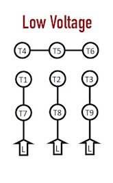
I can't get to the data plate on it (yet), but I removed the cover to the pecker head and the 9 wires were wired for low voltage.

When I tried to run the motor on my RPC (I know my RPC is big enough for the motor), it seemed kind of anemic.

It could be a dying motor, but could the previous owner be correct, that it is 480v, but the wiring for it is still the same a a low voltage diagram? I wouldn't think most 480v motors would even start on 220v.

I'm no expert on 3 phase motors, just know enough to get them running.

image2_motors copy.jpg
 
Last edited:
You only have to Google "Three Phase Motor Connections", and switch to "images" to get a bewildering array of star (WYE) and delta connections, including transformers using both in the same device. While the star and delta connections are easy to understand when drawn out as circuit diagrams spread out in a triangle, the way we see it gets connected is when the ends of the motor windings (shown as coils) are re-arranged so that short metal connection links can be placed between them in various configurations.

The thing to get straight in the mind is "where are the windings between the connection points" we can see ?
Decode where the coils are between the "T" designations.

Next is to know that the connection that uses the LOWER voltages is the DELTA.
The connection that uses the HIGHER voltages is the STAR kind, also called WYE.

Nominally, the difference factor between them is √3 = 1.732, but the range of voltages that can actually be applied is wide, and much messed about with. If a WYE connected motor is changed to DELTA, then it can run on a lower voltage and still deliver the same power. Lower voltage, yes, but it takes higher currents, and the product voltage x current remains the same.

I think the coils in your motor are between..
[T4] and [T7],
[T5] and [T8],
[T6] and [T9].

BUT - I might have that wrong!
The way your diagram is presented is confusing to me.
The WYE windings part on the right would work if links were shown added to join T7-T8-T9 all together, but they are not shown.
Do the lines represent links?


Take great care with the way we express the terms here! A motor connected for LOW voltage is NOT going to run slow if it sees a voltage intended for a WYE connection!!

A "motor connected for LOW voltage" means that we EXPECT a low voltage to be applied. If you put a high voltage on it, you are asking for 1.732 x the rated power! Some folk do this deliberately if their 3-phase supply is low, like about 280V line-to-line, or even if they just want to abuse the motor, and wring more power out of it!

What actual phase-to-phase voltage is coming out of your 3-phase converter supply?

The ways these motors can "seem anemic" or run slow include messed up links, open circuit windings, binding up bearings, metal chip debris and magnetic dust clogging the space between the rotor and the poles, and much more. That said, they are made of fundamental stuff. Iron, copper wires, and insulation. There is not much that can go wrong with them unless they burn up, or the insulation fails.

Any internal dings damage that allow winding wires to connect in ways unintended can represent "shorted turns". They get hot, and the motor limps along.

Test the continuity between the windings. You will discover which terminals only go to a single one other. Use a multimeter. You might have one already. At a pinch, a couple of flashlight batteries, a small bulb, and some hookup wire to make up a crude continuity tester, or use a spare wall-wart charger from an old phone.

There are folk here who have 3-phase and motor stuff saturated through them, and probably built into their DNA. If you get in a knot with this, I am sure they will help.

For now, check all the individual windings are OK, and all read the same value. It will be a low reading of only a few ohms, and there should be no fault unwanted continuity or leaks between them. In the diagram, I have added in the windings, shown as red, yellow, and blue coils. Sorry - the hand wobbled a bit.
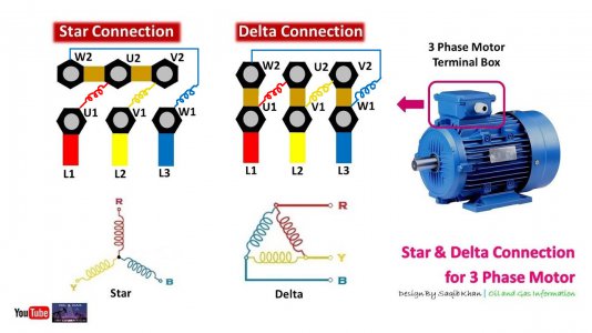
3-phase connections.jpg
 
Last edited:
I'm in a bit of a hurry and don't have time to explain or to vet the content of these videos before posting but they smell like they contain the info I would share if I had more time.


OK - I think @strantor has got it right! The motor is always fundamentally a WYE connection.
T7-T8-T9 are always connected together internally.
The way it gets to have a dual-voltage configuration is by having dual sets of coils.
They are connected in series for the high voltage connection.

That said, the very same approach to finding out what is the problem with it does not change. Take out the links. Test for continuity of the windings. Verify none are open circuit. Check for insulation between them.
Our thanks to @strantor for finding this. :)
 
Last edited:
OK - I think @strantor has got it right! The motor is always fundamentally a WYE connection.
T7-T8-T9 are always connected together internally.
The way it gets to have a dual-voltage configuration is by having dual sets of coils.
They are connected in series for the high voltage connection.

That said, the very same approach to finding out what is the problem with it does not change. Take out the links. Test for continuity of the windings. Verify none are open circuit. Check for insulation between them.
Our thanks to @strantor for finding this. :)
Checking with a DMM is of course a good call, and a good no-go-only test (as opposed to go/no-go). It will immediately tell you if you have an open winding or a winding directly shorted to case/ground. But just because a DMM indicates a motor is "good" doesn't mean it's good.

In the case of the internally shorted windings you mentioned earlier (a few turns of a winding bypassed, or windings shorted to other windings) a DMM almost always doesn't have the necessary resolution to tell you that. For that you need a milliohmmeter. A DMM (analogous to a tape measure) might report something like 0.2 ohms each phase, making it seem ok, while a milliohmmeter (analogous to a micrometer) might reveal that two windings are 0.1995 ohms and 0.2025 ohms while the third winding is 0.1530 ohms (a difference of >25% and a big deal).

In the case of weak insulation resistance, the DMM might indicate that all windings have >1Mohm to case, which seems good, but the DMM only uses about 1V to measure resistance, so what it can't show you is that your insulation has pinholes and above 200V the windings start arcing to ground. For this reason there is another device (Megohmmeter aka "Megger") which basically the same thing as an ohmmeter or DMM except it uses up to 1,000v to check resistance.

I realize I'm probably not telling you anything you don't already know; this is more for @MyLilMule and/or anyone else who might not know.
 
This is not the can of worms I was expecting to open. LOL!

A lot to digest. But, was my original question answered? I don't see it within the theory and testing methodology. I only included the diagram to communicate that the Low Voltage diagram is how the motor is wired - I grabbed it off of Google. I should have clipped out the rest (I edited the original post) as that may have led to some confusion of what I was asking.

Can a motor, wired to the 3 phase input in what a typical diagram would consider "Low Voltage" actually be expecting 480 volts? Do those motors exist? If the simple answer is "no" - then I can worry about the causes when I need to.
 
This is not the can of worms I was expecting to open. LOL!
Sorry, didn't mean to complicate things.
A lot to digest. But, was my original question answered?
I didn't understand your original question; I should have asked for clarification.
.Can a motor, wired to the 3 phase input in what a typical diagram would consider "Low Voltage" actually be expecting 480 volts? Do those motors exist? If the simple answer is "no" - then I can worry about the causes when I need to.
With 95% probability: no.
The other 5% involves motor having been rewound in the past in some wacky way.

I would perform the DMM tests suggested by @graham-xrf and post the results. That will hopefully be enough info to say if the motor is bad.
 
In normal terminology, if a motor is wired for "low voltage" it will run on 240 volts. (actually 200 to around 280) If it is wired for high voltage, it is rated for 480 volts. (actually 410 to almost 500 volts) FWIW, I have worked on motors rated for 2300, 4160, and 13.8 KV, were they high or low voltage?

There are many motor connections, most industrial motors, in the States, are 9 wire, wye connected. But by a long measure, not all. Many are wound for special use using different, and confusing, connections. In any case, the motor name plate will contain the required information.

I concur with the above about using a megger versus an ohm meter. Checking each winding to ground as well as from winding to winding. With everything disconnected, of course. . .

.
 
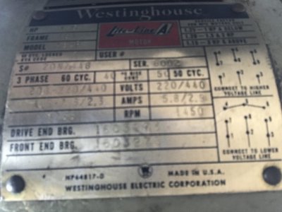
No worries. It is ALL good information! I will definitely do that check once I am able. It may be some time, however. The machine is sitting on my trailer out back under a tarp. Knowing that it is not likely is good to know, at least from a "from the factory" way. This could have been rewound at some point, because I did manage to find the data plate.

IMG_9113.jpg

Best photo I could get. Had to slide my phone underneath the motor and got lucky.

I also uploaded a short video of what I mean my anemic. As soon as I engage the power feed, the motor bogs. Could be bearings, but everything seems to turn nicely until then. But it still seems kind of slow at this speed selection.


A lot to consider once I finally get it inside. I doubt I will have this motor fixed. More likely replace it with a newer 3 phase.
 
In normal terminology, if a motor is wired for "low voltage" it will run on 240 volts. (actually 200 to around 280) If it is wired for high voltage, it is rated for 480 volts. (actually 410 to almost 500 volts) FWIW, I have worked on motors rated for 2300, 4160, and 13.8 KV, were they high or low voltage?
I know you know this but "Normal" terminology depends on the industry or area. HV/LV takes on a different meaning all over again if you're talking about hobby plane motors for example.

Those motors you worked on, I think a lineman would call "medium voltage."
 
Back
Top