Machine Wiring Help

Okay I found it. Turned out to be the 24vac connection at terminal 30 on the transformer not being seated correctly. You cant see the terminal pocket without a mirror so it wasn't getting clamped even though it felt tight. Everything now works as it should.

Thanks for everyones help. In a way i'm glad this happened as I now have a better understanding of how the motor control and switching works and how to troubleshoot.

Thanks again.

Jay
 
Glad you got it all sorted out.

Okay I found it. Turned out to be the 24vac connection at terminal 30 on the transformer not being seated correctly. You cant see the terminal pocket without a mirror so it wasn't getting clamped even though it felt tight. Everything now works as it should.

Thanks for everyones help. In a way i'm glad this happened as I now have a better understanding of how the motor control and switching works and how to troubleshoot.

Thanks again.

Jay
 
I have another question. I have (2) extra contactors so I was thinking I could use these to power up the stepper motor power supplies. I have (2) 115amp 110vac lines to power the steppers, coolant pump and PS for the breakout board. The contactors are rated at 20A. What would be the best way to wire these to the same switch circuit?

Jay


Would you lay out all of the components (switches, relays, step drives, etc.) that you have to work with on a table and take a picture of them. I need to see exactly what you have to help you make everything work together.

In general, you want to have a Control Power Relay that powers up the control voltage to run the rest of the system. This relay can also power up the the step motor power supply(s). Normally I use only one step motor power supply to power up all of the step motor drives. This really depends on what hardware you have.


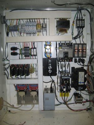
Below is a picture of a control panel I built to run a 4 axis router. The heavy power stuff on the right is to run the 10HP spindle VFD and the 5HP vacuum pump. There is a fused disconnect on top of the box that powers up the whole system. In the center, the black and blue things are the 70VDC power supply for the step drives. The control circuitry is all on the left. The step drives are left, near center. This is to give an idea of what needs to go into the system to have full, and safe control over the machine. The switches for the controls are in another box. Normally I would have used a bigger enclosure for the build, but this is what I had to work with, it's a bit crowded.


adxpanel.jpg
 
Jom, i cannot layout all my component as they are mostly installed in enclosures. Each stepper, xyz&a have their own PS and driver. Im splitting the load between two 15A circuits. I was thinking since I have the extra relays I could use them to power up the whole system with one start button plus it would all be on the same estop as well.

To start/stop three relays with one switch corcuit would the coils be wired in parallel and the holding circuit wired in series?

Jay

Please be very careful feeding from 2 separate 120 circuits, they could be connected to opposite sides of the breaker panel and thus would have 240 VAC between them. You can check this by putting a volt meter between the 2 hot legs on the plugs (the small lug of the plug if it is wired correctly). If they are the same phase, the reading on the meter should be near zero, if not you will have around 240V. Things can get ugly in a hurry if you are connected to opposite phases and don't have proper isolation.

Yes, you can power up everything in the way you described. It looks like you have terminals 43 and 44 available on KM1 to power up the other 2 relays. This will make KM1 the control power relay, thus when you hit the E-stop everything will power down.

Connect 24VAC to terminal 43 and connect 44 to A1 on the other 2 relays, connect A2 on the relays to the 24VAC common. You could add a couple of switches between 44 and A1 on the 2 relays, this would allow you to turn off the devices connected to those relays if you don't need them for what you are doing at the time.
 
Thanks Jim. As as contractor for 30 years I am quite familiar with residential wiring. Electronics not as much but i try to be careful.

Jay
 
Thanks Jim. As as contractor for 30 years I am quite familiar with residential wiring. Electronics not as much but i try to be careful.

Jay


You're welcome. Sounds like you have it under control. You never know what the skill level is of the person on the other end of the thread. Glad I could be of some help. If you get stuck, you can always shoot me an email or a PM if I don't respond here.
 
Back
Top