Machine Wiring Help

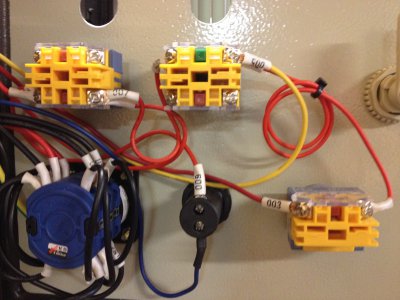
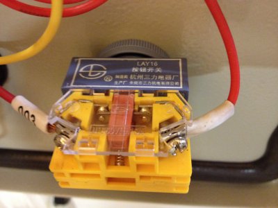
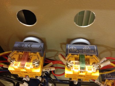
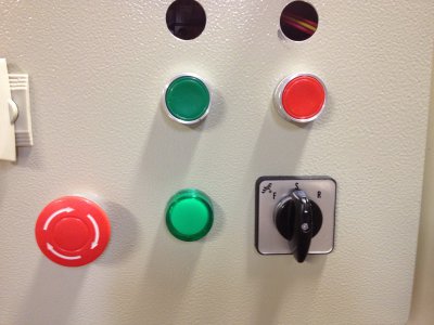
SB1 and SB3 are shown as normally closed estops. Can you take a picture straight on of the button wiring and terminals? And of the button themselves from the front?

Both? There is only one e-stop.
 
SB1 and SB3 are shown as normally closed estops. Can you take a picture straight on of the button wiring and terminals? And of the button themselves from the front?

SB1 is the e-stop (1st photo right), SB2 is the green start button (1st photo middle), SB3 is the red stop button (1st photo left)

IMG_0806.JPGIMG_0807.JPGIMG_0808.JPGIMG_0809.JPG

IMG_0806.JPG IMG_0807.JPG IMG_0808.JPG IMG_0809.JPG
 
I can trace through SB2 and it all looks right, but it's hard to see the wiring on SB3. Coming off of SB3 on the lower left terminals you should have two wires; one will go to the green light and the other will go to the coil terminal on the contactor (lowest two terminals, near the colored plug showing the coil voltage of 24VAC). The other coil terminal should go to ground. Can you trace that part of the circuit and see if it is correct? It also looks like there is a wire going to one of the upper terminals on SB3?

SB1 is the e-stop (1st photo right), SB2 is the green start button (1st photo middle), SB3 is the red stop button (1st photo left)
 
It looks like one side of the 24VAC should be grounded, this would be normal. The other side should go to wire 1, then through the breaker, and exits the breaker as wire 3. Follow the schematic through with your volt meter and see at what point you lose power.

With one voltmeter probe on the common terminal of the transformer, 30 or 31, I can't tell from the pictures, the wire may be labeled 2. With the green button pressed, you should have 24VAC on wire 9, and at terminal A1 of KM1. Terminal A2 on KM1 should be directly connected to the common terminal of the transformer.

If you don't have 24VAC on wire 9 then check at wire 5.
 
Last edited:
I can trace through SB2 and it all looks right, but it's hard to see the wiring on SB3. Coming off of SB3 on the lower left terminals you should have two wires; one will go to the green light and the other will go to the coil terminal on the contactor (lowest two terminals, near the colored plug showing the coil voltage of 24VAC). The other coil terminal should go to ground. Can you trace that part of the circuit and see if it is correct? It also looks like there is a wire going to one of the upper terminals on SB3?

There are two red wires off the left side of SB3, one to the green light the other to the lower left bottom terminal on the contactor KM1. On the lower right upper terminal of KM1 there are two blue wires, one goes the the green light and the other goes to terminal 30 of the transformer.

Hope that makes sense.

Jay


The blue wire is the 24VAC common. wire 009 should go to the lower left bottom terminal on KM1, this terminal should be labeled A1 or A2
 
Thanks for everyone's help so far. I have to call it a night. Tomorrow I will make a sketch of the wiring and see if that helps clear things up.

Jay
 
The blue wire is the 24VAC common. wire 009 should go to the lower left bottom terminal on KM1, this terminal should be labeled A1 or A2

Wire 009 goes to A1. The blue wire goes to A2. With the green button pressed I get 24vac on wire 009 at A1.

Jay
 
Wire 009 goes to A1. The blue wire goes to A2. With the green button pressed I get 24vac on wire 009 at A1.

Jay

OK, that's great.

Is the blue wire connected to the transformer?

Does the green light come on when you push the green button?

With the green button pushed, do you have 24VAC between A1 and A2 on KM1?

If all of the above are true, then the contactor armature is probably jammed. This is not an uncommon problem on Chinese contactors. With power disconnected from the machine. Loosen the contact block mounting screws a bit, and wiggle it a bit while testing the armature freedom by pushing the little black button on the contactor face. Re-tighten the screws when thing are aligned properly.
 
I wiil check that out tonight. I'm beginning to better understand how the switch circuit works. I'm suspecting it may be the 24vac common connection at A2. I replaced this wire with a longer lead and the spade connectors are a little wide so I may not have it seated properly. I need to pick ip some longer test leads to better reach the coil terminals.

Jay
 
Back
Top