Lets see if I can tickle your OCD a little.
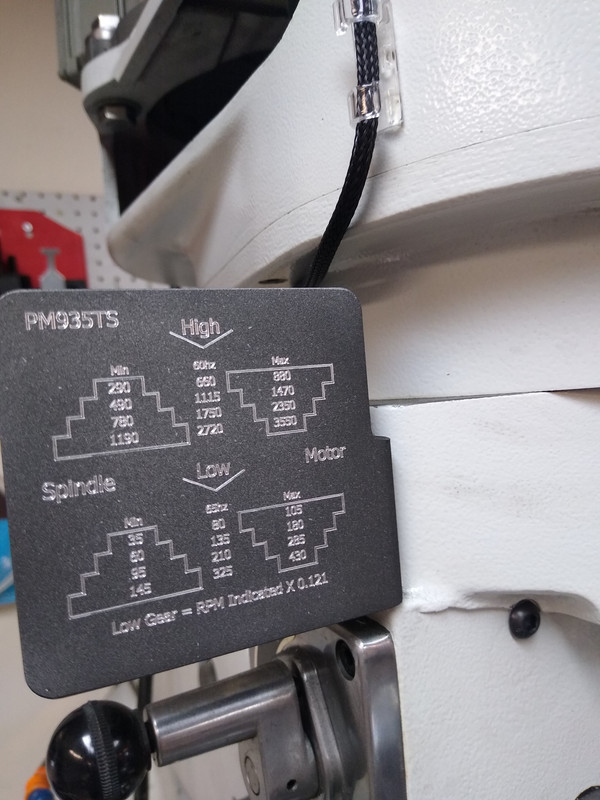
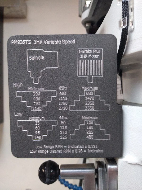
I don't know your machine but because you reference hz, I'll assume it's 3 phase powered by a VFD.
On the plaque, the center column RPM (Nominal RPM?) indicates @65hz. Why not 60hz?
When I read "Minimum" and "Maximum" I want to know "at what frequency?". I would replace min and max with XXhz. Or, XXhz MIN. and XXXhz MAX. YMMV
The nomenclature at the bottom is too cryptic for me to decipher. I'm curious, if you want to explain.
Basically, for the middle column I used the RPM from the stock PM label. I set the corresponding pulley/belt arrangement, turned on the spindle and adjusted the potentiometer to the get my tachometer to the RPM indicated on the stock decal, then took the frequency indicated on the front of the VFD. Rounded of course. When set to the factory speeds, they were all oddly alot closer to 65hz than 60hz.
For the min and max, I just turned the POT all the way up, and all the way down recording the speeds from my tach.
I could have, and perhaps maybe should have engraved the frequencies at min/max speeds. But, I guess since I set the upper and lower limits of the VFD to 30hz and 80hz, figured I'd know those frequencies anyway.
Either way, I'm not making a 3rd one.
")
I found another project for the day.
I made a copy of the Or3gun marine spacer tube for my shotgun. Just need to go test it out.

The info at the bottom is for calculating the spindle speed in back-gear.
The tach pickup magnet is on the pulley, so doesn't read accurately in back gear. Those are formulas for getting the correct spindle speed in back gear.
The RPM displayed on the tach multiplied times 0.121 = the actual spindle speed. For example, in back-gear, 2500 on the tach = 302.5 rpm.
Or, to set a specific spindle speed in back gear, you can multiply the speed you desire times 8.26, then dial the tach to that value.
For example, If I want a back-gear speed of 122 rpm, I would multiply 122 x 8.26, which = 1007.72. so I would set the tach to 1008 rpm.