- Joined
- Oct 30, 2019
- Messages
- 197
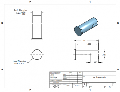
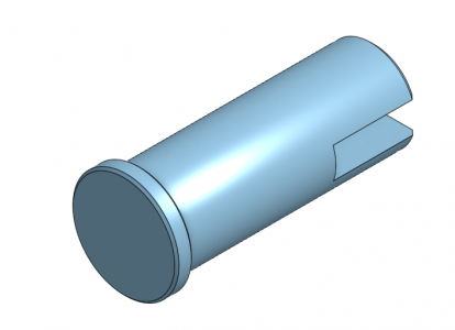
My dad has been hand-making some parts for customizing certain pieces of outdoor equipment. His historical process is just using a hacksaw and files to cut off and shape pieces of round aluminum stock.
As he has refined his design, he has also wanted more consistency batch-to-batch, and during a visit this week we were talking about how we can make some batches up in the shop here.
The part involves 3 main machining steps:
- Turning the diameters required (1/2" diameter round aluminum stock, turned down to .401"diameter except for a .125-long" shoulder left at the full 1/2" diameter at one end)
- Chamfering and Parting off
- Cutting a slot in one end
However, there is a problem with the order of operations. The overall length of the part is only 1.25" - too short to hold in a collet block with the shoulder at one end, which would have been the easiest way to hold it at the mill.
Holding the round stock in the mill (before cut to length) requires moving between the mill and lathe more often than is convenient for trying to batch 5 to 15 of these in a short run.
The answer we came up with was a jig that could hold a small quantity in the mill for slotting.
My dad was thinking a jig where the top is totally removed and clamps the parts, however I preferred a "flexture" where the jig could stay clamped and trammed in the mill.
The first step was determining the overall length and placement/spacing of the features. The length was dictated by what piece of aluminum bar I had in the scrap bin. The other features were:
- Set the centerline of the parts a known distance from the top for easier alignment of the slitting saw. We went with 0.5" from the top of the fixture
- 5 clamping screws (1/4-20 cap screws found in assorted inventory), biased towards the slotted side/front of the fixture
- 4 holding positions drilled with a Y drill (.404)
- Slot cut to ~ 2/3 the thickness of the fixture
The overall fixture length was ~ 5.25", leading to a pretty inflexible layout of the features.
The process started with approximate squaring of a piece of scrap from the bin, in the horizontal bandsaw. One side was flattened on the mill to provide a reference surface for the bottom of the fixture.
Holes were drilled from the top down for the 1/4-20 tapped holes; and with a Y drill from the front. The latter holes came out closer to .402 or .403 instead of .404, which gave perfect .001-002 clearance for holding the parts. If the hole had been larger, the required specs allowed for the turned diameter to be increased slightly (to .402 or .403 as-needed for proper clamping in the jig).
The holes were chamfered, and at this point ready for slotting. This is where I started taking pictures
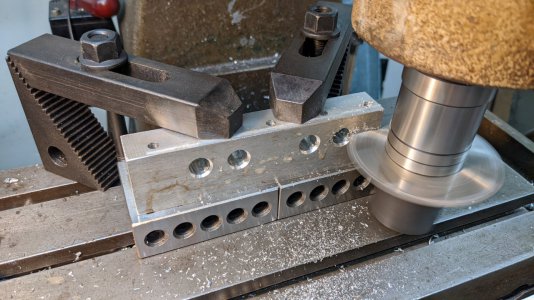
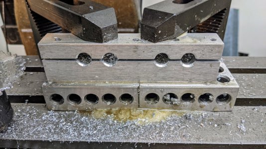
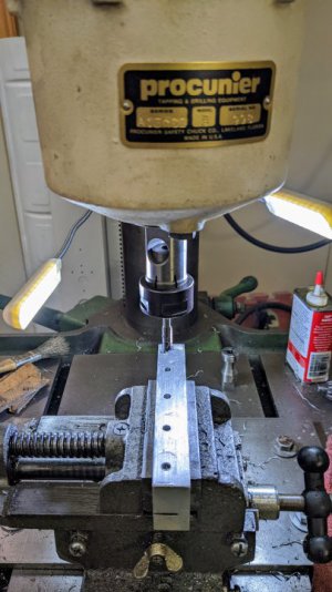
Now tapping the 5x 1/4-20 holes from the top. Based on the length of the threads, I decided to install the tapping head in the drill press for this. The 1/4-20 tap I grabbed was a gun tap, which worked well for power tapping these through-holes.
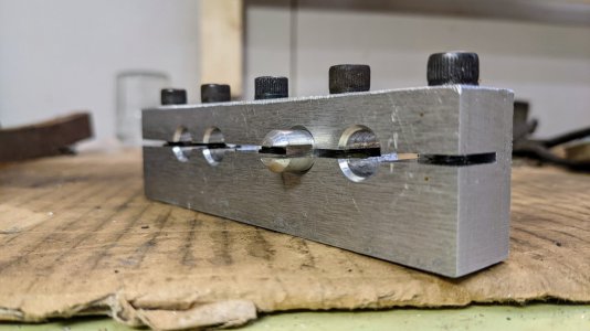
After some deburring and drilling the 1/4" clearance hole in the top portion of the clamping screw locations, the fixture was ready for use. Here it is with a finished part for demonstration purposes:
And the next day in the mill with the first batch of parts:
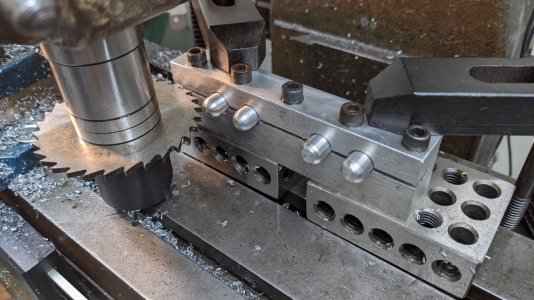
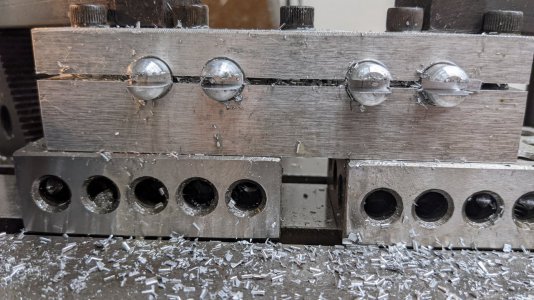
This worked a treat. It is made of aluminum, so of course we need to be careful not to force any parts in and create burrs/galling. And if this was going to see more than occasional home shop use, it would be steel instead of aluminum to avoid wear.
The tolerances on the resulting part are very flexible, so this solution should work well when we occasionally want to make more. I am extremely pleased with how well it worked and how positively the clamping worked out, given that the proportions of the fixture were totally made up on the spot based on intuition (or lack thereof).
We greased the clamping screws on the threads and under the heads to reduce wear and prevent galling - but this also may have helped increase the amount of clamping at reasonable torques. We did not need to go more than moderately-snug on the clamping screws to hold the workpieces more firmly than we could budge - this seemed perfect.
You bet that if I ever need to slot small parts for a project of my own -- I will do my best to design such a project for those parts to be .401" on some feature to allow reuse of this fixture!
Thanks for reading.
Tools used:
- Logan 200 lathe
- Start-Rite H175W horizontal bandsaw
- Norsemen drill index
- Chicago-Latrobe tap+drill set
- Rockwell 21-100 mill
- cheap import 123 blocks
- The usual cheap strap clamp set
- Procunier #3 tapping head
- Powermatic 1200 drill press
As he has refined his design, he has also wanted more consistency batch-to-batch, and during a visit this week we were talking about how we can make some batches up in the shop here.
The part involves 3 main machining steps:
- Turning the diameters required (1/2" diameter round aluminum stock, turned down to .401"diameter except for a .125-long" shoulder left at the full 1/2" diameter at one end)
- Chamfering and Parting off
- Cutting a slot in one end
However, there is a problem with the order of operations. The overall length of the part is only 1.25" - too short to hold in a collet block with the shoulder at one end, which would have been the easiest way to hold it at the mill.
Holding the round stock in the mill (before cut to length) requires moving between the mill and lathe more often than is convenient for trying to batch 5 to 15 of these in a short run.
The answer we came up with was a jig that could hold a small quantity in the mill for slotting.
My dad was thinking a jig where the top is totally removed and clamps the parts, however I preferred a "flexture" where the jig could stay clamped and trammed in the mill.
The first step was determining the overall length and placement/spacing of the features. The length was dictated by what piece of aluminum bar I had in the scrap bin. The other features were:
- Set the centerline of the parts a known distance from the top for easier alignment of the slitting saw. We went with 0.5" from the top of the fixture
- 5 clamping screws (1/4-20 cap screws found in assorted inventory), biased towards the slotted side/front of the fixture
- 4 holding positions drilled with a Y drill (.404)
- Slot cut to ~ 2/3 the thickness of the fixture
The overall fixture length was ~ 5.25", leading to a pretty inflexible layout of the features.
The process started with approximate squaring of a piece of scrap from the bin, in the horizontal bandsaw. One side was flattened on the mill to provide a reference surface for the bottom of the fixture.
Holes were drilled from the top down for the 1/4-20 tapped holes; and with a Y drill from the front. The latter holes came out closer to .402 or .403 instead of .404, which gave perfect .001-002 clearance for holding the parts. If the hole had been larger, the required specs allowed for the turned diameter to be increased slightly (to .402 or .403 as-needed for proper clamping in the jig).
The holes were chamfered, and at this point ready for slotting. This is where I started taking pictures


Now tapping the 5x 1/4-20 holes from the top. Based on the length of the threads, I decided to install the tapping head in the drill press for this. The 1/4-20 tap I grabbed was a gun tap, which worked well for power tapping these through-holes.

After some deburring and drilling the 1/4" clearance hole in the top portion of the clamping screw locations, the fixture was ready for use. Here it is with a finished part for demonstration purposes:

And the next day in the mill with the first batch of parts:


This worked a treat. It is made of aluminum, so of course we need to be careful not to force any parts in and create burrs/galling. And if this was going to see more than occasional home shop use, it would be steel instead of aluminum to avoid wear.
The tolerances on the resulting part are very flexible, so this solution should work well when we occasionally want to make more. I am extremely pleased with how well it worked and how positively the clamping worked out, given that the proportions of the fixture were totally made up on the spot based on intuition (or lack thereof).
We greased the clamping screws on the threads and under the heads to reduce wear and prevent galling - but this also may have helped increase the amount of clamping at reasonable torques. We did not need to go more than moderately-snug on the clamping screws to hold the workpieces more firmly than we could budge - this seemed perfect.
You bet that if I ever need to slot small parts for a project of my own -- I will do my best to design such a project for those parts to be .401" on some feature to allow reuse of this fixture!
Thanks for reading.
Tools used:
- Logan 200 lathe
- Start-Rite H175W horizontal bandsaw
- Norsemen drill index
- Chicago-Latrobe tap+drill set
- Rockwell 21-100 mill
- cheap import 123 blocks
- The usual cheap strap clamp set
- Procunier #3 tapping head
- Powermatic 1200 drill press


