- Joined
- Aug 3, 2017
- Messages
- 2,437
SO, Full backstory: https://www.hobby-machinist.com/threads/how-do-i-make-this-gib-materials-order-of-operations.79423/
For those who don't want to read, my 14" Reed Prentice lathe's compound slide gib was pretty messed up, so I opted to make a new one! I am following some of the advice in that thread.
First, I ordered a piece of Class 40 Cast Iron from Speedy Metals.
Next, I cleaned my table and retrammed the head (I used this https://www.edgetechnologyproducts.com/pro-tram-system-01-000-10-000-09-000/). I'd prevoiusly had the whole machine apart, so the head was quite a bit out of tram, despite aligning it with a square.

While that was happening, I also cut my 24" piece of stock in half. I ordered 1.25" square stock, 24" long. I need ~10-11 inches (and much less than 1.25"!), but ordered 2x as much so that I have 2-4 chances in case I mess up.

The stock was actually REALLY flat from speedy metals, surprisingly so! On the table, I couldn't get .003 shim stock under it anywhere! I flattened 1 side to be a reference surface anyway, but I had to swap 3 clamps around. I ended up taking ~.008 off, but the 2nd pass was likely unnecessary.

I flipped it over and did it again") This will be the new 'top' of my gib.
This will be the new 'top' of my gib.

Next, I indicated along the back side to minimize the amount of material I needed to take off. I'd initially done this with a combo square off the front of the table and was only off ~3 thou over the whole length! A little bit of tapping, and it was just about perfect.

Next, I cut enough material off the back to remove the rounded top. Initially, I'd planned on this being the dovetail side, but it isn't going to work out that way, so cutting this much material off ended up being unnecessary.

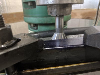
Next, I was going to cut the dovetail, however ran into a huge problem: I have a riser block, so even with the spindle all the way extended, the table all the way up, and quite a bit of stickout, I'm still about 3/8" too high!

SO, I'm going to cut the "flat"/"overhang" side on the back. I can use the same endmill as before and just take the 0.130 off the back instead. I am just going to use 1-2-3 blocks under the stock when I flip it around to do the dovetail side.
I came up with ANOTHER significant issue however that I wouldn't mind feedback on. The nose of the dovetail (the acute side) is rounded over a bit, so measurements off of it aren't terribly accurate. Any amount that I miss this 'radius' is going to significantly alter the size. At the moment, my solution is going to be to just make it 'close' but a bit oversized. Then, I plan on just doing a set of test/fit cycles. I don't have a good, repeatable way to put it back on the mill (since I'll have removed most of the material from the 'bottom' as it sits on the mill now), so my ideas are:
1- If I end up too large, put some ~600 grit sandpaper on my surface plate, and take a few swipes at a time off the dovetail.
2- If I end up being too 'small', take some brass shim-stock and loctite it to the flat (which is not a moving surface).
Thoughts?
For those who don't want to read, my 14" Reed Prentice lathe's compound slide gib was pretty messed up, so I opted to make a new one! I am following some of the advice in that thread.
First, I ordered a piece of Class 40 Cast Iron from Speedy Metals.
Next, I cleaned my table and retrammed the head (I used this https://www.edgetechnologyproducts.com/pro-tram-system-01-000-10-000-09-000/). I'd prevoiusly had the whole machine apart, so the head was quite a bit out of tram, despite aligning it with a square.
While that was happening, I also cut my 24" piece of stock in half. I ordered 1.25" square stock, 24" long. I need ~10-11 inches (and much less than 1.25"!), but ordered 2x as much so that I have 2-4 chances in case I mess up.
The stock was actually REALLY flat from speedy metals, surprisingly so! On the table, I couldn't get .003 shim stock under it anywhere! I flattened 1 side to be a reference surface anyway, but I had to swap 3 clamps around. I ended up taking ~.008 off, but the 2nd pass was likely unnecessary.
I flipped it over and did it again
This will be the new 'top' of my gib. Next, I indicated along the back side to minimize the amount of material I needed to take off. I'd initially done this with a combo square off the front of the table and was only off ~3 thou over the whole length! A little bit of tapping, and it was just about perfect.
Next, I cut enough material off the back to remove the rounded top. Initially, I'd planned on this being the dovetail side, but it isn't going to work out that way, so cutting this much material off ended up being unnecessary.
Next, I was going to cut the dovetail, however ran into a huge problem: I have a riser block, so even with the spindle all the way extended, the table all the way up, and quite a bit of stickout, I'm still about 3/8" too high!
SO, I'm going to cut the "flat"/"overhang" side on the back. I can use the same endmill as before and just take the 0.130 off the back instead. I am just going to use 1-2-3 blocks under the stock when I flip it around to do the dovetail side.
I came up with ANOTHER significant issue however that I wouldn't mind feedback on. The nose of the dovetail (the acute side) is rounded over a bit, so measurements off of it aren't terribly accurate. Any amount that I miss this 'radius' is going to significantly alter the size. At the moment, my solution is going to be to just make it 'close' but a bit oversized. Then, I plan on just doing a set of test/fit cycles. I don't have a good, repeatable way to put it back on the mill (since I'll have removed most of the material from the 'bottom' as it sits on the mill now), so my ideas are:
1- If I end up too large, put some ~600 grit sandpaper on my surface plate, and take a few swipes at a time off the dovetail.
2- If I end up being too 'small', take some brass shim-stock and loctite it to the flat (which is not a moving surface).
Thoughts?