- Joined
- Jan 20, 2016
- Messages
- 173
Please bear with me, this will be long and photo heavy if I can figure out how to do this correctly.
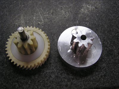
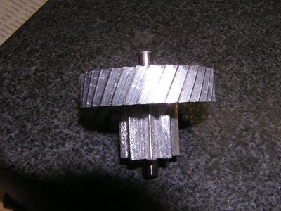
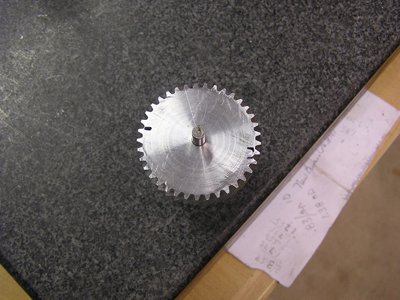
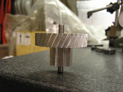
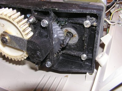
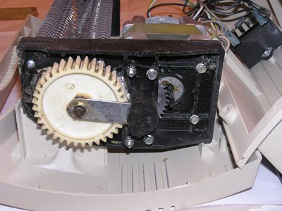
I have had a 12 sheet crosscut paper shredder for about 10 years. Was shredding 6 years of old financial / tax stuff when I jammed it up and heard the gears jump. Took it apart and found this plastic helical / straight gear was the problem – it had 3 teeth torn off.
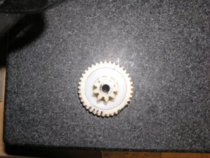
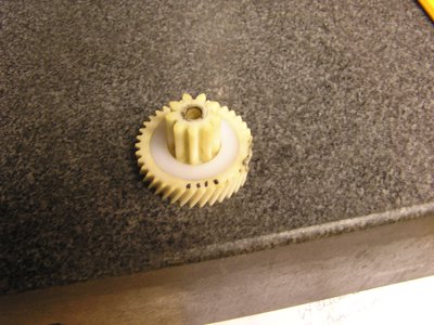
Searching the internet and calling the OEM only confirmed that the gear could no longer be purchased. Equivalent paper shredder was about $200, which seems pretty expensive for a stupid plastic gear. So looked around on the hobby machine shop pages, others, and Youtube videos, I found what appeared a simple method for making a gear hob, plus it looked easy to cut the teeth with the tools I already had. Keep in mind that while I used to be a tool & die maker in another lifetime, I never attempted to make a gear before. Decided to try it, and if it didn’t work I could go buy the new shredder then.
Since the 9 tooth straight gear was still good, I was originally going to just make a band for the 37 tooth helical portion. I don’t have the special equipment to cut a helical gear, so decided to approximate it as just an angled straight gear profile. The theory is that you make a 5 tooth gear hob where the center tooth cuts the most, but the 2 teeth on either side continue to refine the shape of adjacent gears till they match the elliptical shape automatically. Only trick is to get the spacing between teeth correct, and the width of the teeth correct. So I did the math for a 37 tooth and roughed out a O-1 gear hob.
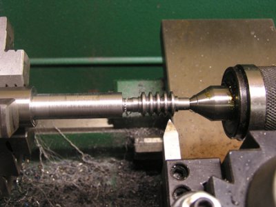
Went back and measured the depth of each tooth with a pin, was using the dial indicator to give me the pitch between teeth. Worked pretty good! I was felly really good about this plan right about now.
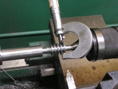
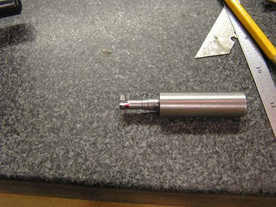
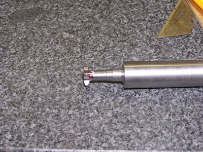
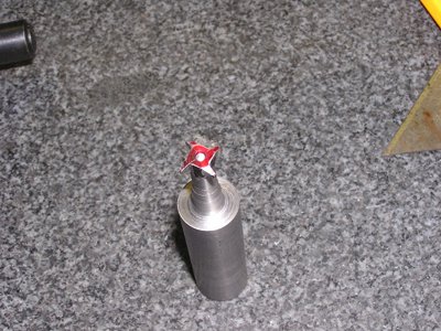
That is it worked great till I held the plastic gear up to my new hob and discovered that the spacing was at least .010 per tooth too small! Apparently the formulas I used were for straight tooth gears only, and the angled gear I need had a cosine error that I ignored. I had about 3 hours into the hob, so decided to cannibalize it and just go to single tooth fly cutter type gear hob. Was able to use the original hob and just make the diameter a little smaller - ended up with a nice little 4 tooth cutter ready for the propane torch heat treat / quench.
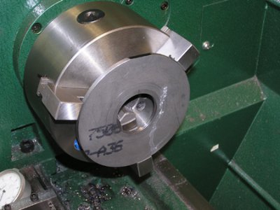
Next problem was that the 5C collet spin indexers all only come with 36 holes for 1° indexing, and don’t come with the sides milled to hold in a vise. So first I took the indexer apart and clamped it to an angle plate with 123 blocks under each end of the spindle. That allowed me to clean up the first side, then flipped it over and did 2nd side to same dimension. After the rough I took a nice finish cut on each side (no photos). Now I need to make an indexing plate with 37 holes in it. Found a piece of 3/16 plate in the scrap pile and sawed it into a rough circle. Had read before on the hobby sites that it worked to push the disk up against chuck jaws with a center if you took light cuts, so tried it. I could only take .010 deep cuts, but did it no problem. Only took about 20 minutes to make it round and too size.
I had to reverse the jaws so could now hold it on the OD to bore the ID a light tap fit for the spindle.
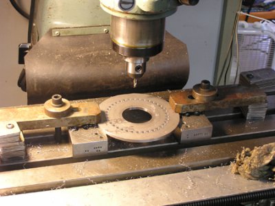
Next I set it up in the mill and swept the ID, then used the readout to center-drill, drill, end mill to location and near size, counter sink and ream all 37 holes. That took about 2 hours alone! But I now have a finished indexer 37 hole plate.
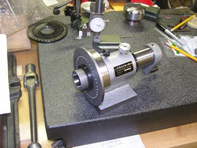
Now when I put the indexer back together I am finally ready to make the gear itself.
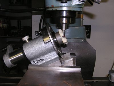
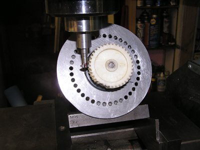
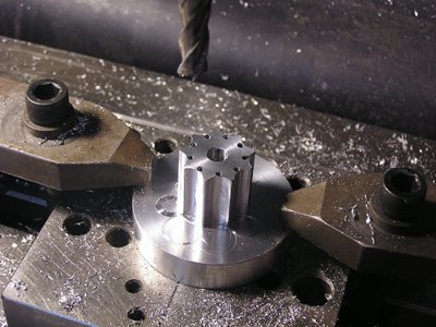
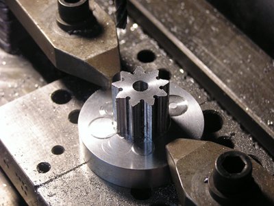
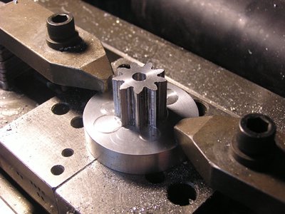
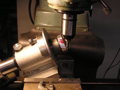
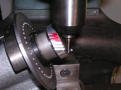
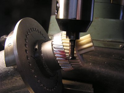
Still not certain this would work; I set up the indexer on the plastic gear to make sure this will work. This should give you an idea of how I am going to try to cut the angled tooth portion.
Will finish this later...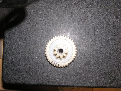
I have had a 12 sheet crosscut paper shredder for about 10 years. Was shredding 6 years of old financial / tax stuff when I jammed it up and heard the gears jump. Took it apart and found this plastic helical / straight gear was the problem – it had 3 teeth torn off.


Searching the internet and calling the OEM only confirmed that the gear could no longer be purchased. Equivalent paper shredder was about $200, which seems pretty expensive for a stupid plastic gear. So looked around on the hobby machine shop pages, others, and Youtube videos, I found what appeared a simple method for making a gear hob, plus it looked easy to cut the teeth with the tools I already had. Keep in mind that while I used to be a tool & die maker in another lifetime, I never attempted to make a gear before. Decided to try it, and if it didn’t work I could go buy the new shredder then.
Since the 9 tooth straight gear was still good, I was originally going to just make a band for the 37 tooth helical portion. I don’t have the special equipment to cut a helical gear, so decided to approximate it as just an angled straight gear profile. The theory is that you make a 5 tooth gear hob where the center tooth cuts the most, but the 2 teeth on either side continue to refine the shape of adjacent gears till they match the elliptical shape automatically. Only trick is to get the spacing between teeth correct, and the width of the teeth correct. So I did the math for a 37 tooth and roughed out a O-1 gear hob.

Went back and measured the depth of each tooth with a pin, was using the dial indicator to give me the pitch between teeth. Worked pretty good! I was felly really good about this plan right about now.

That is it worked great till I held the plastic gear up to my new hob and discovered that the spacing was at least .010 per tooth too small! Apparently the formulas I used were for straight tooth gears only, and the angled gear I need had a cosine error that I ignored. I had about 3 hours into the hob, so decided to cannibalize it and just go to single tooth fly cutter type gear hob. Was able to use the original hob and just make the diameter a little smaller - ended up with a nice little 4 tooth cutter ready for the propane torch heat treat / quench.


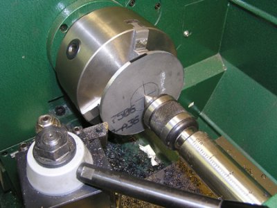
Next problem was that the 5C collet spin indexers all only come with 36 holes for 1° indexing, and don’t come with the sides milled to hold in a vise. So first I took the indexer apart and clamped it to an angle plate with 123 blocks under each end of the spindle. That allowed me to clean up the first side, then flipped it over and did 2nd side to same dimension. After the rough I took a nice finish cut on each side (no photos). Now I need to make an indexing plate with 37 holes in it. Found a piece of 3/16 plate in the scrap pile and sawed it into a rough circle. Had read before on the hobby sites that it worked to push the disk up against chuck jaws with a center if you took light cuts, so tried it. I could only take .010 deep cuts, but did it no problem. Only took about 20 minutes to make it round and too size.

I had to reverse the jaws so could now hold it on the OD to bore the ID a light tap fit for the spindle.

Next I set it up in the mill and swept the ID, then used the readout to center-drill, drill, end mill to location and near size, counter sink and ream all 37 holes. That took about 2 hours alone! But I now have a finished indexer 37 hole plate.

Now when I put the indexer back together I am finally ready to make the gear itself.

Still not certain this would work; I set up the indexer on the plastic gear to make sure this will work. This should give you an idea of how I am going to try to cut the angled tooth portion.


Will finish this later...



 Great job!