- Joined
- Jan 20, 2013
- Messages
- 273
I am building a model marine engine from plans in a book called "Working Steam Engines" by Rudy Kouhoupt. I thought I would try to give something back to the forum by documenting how I made two the small connecting rods for this little steam engine.
Sorry I didn't take photos of these first steps but, I had previously cut two pieces of bronze to size. I then drilled the holes for the little 1-78 screws more than 1/2 an inch deep and then I drilled the #49 clearance holes pretty much 1/4" deep. I then carefully tapped the 1-78 holes. Next I used a slitting saw to cut the 1/4" connecting rod cap off the rod. I put the cap back on the same way it was sawed off with the 1-78 screws. I stamped a small witness mark on each rod with cap so that I could reassemble them the exact same way everytime. I Dykemed one of the parts and scribed the location of the holes and the outline of the desired shape.
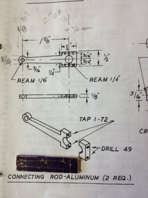
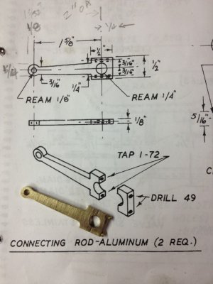
The photo below shows the blueprint for the parts and one of the two blanks for the connecting rods.
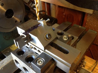
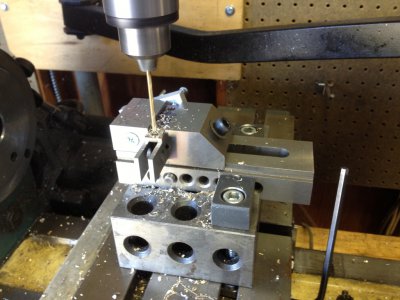
In the photo above I have mounted my vise on the mill and carefully dialed it in. Because I am making two parts and I want them the same, I have mounted a stop on the back side of the vise. I used a center drill to mark the spot of the large hole. I am about to drill through the part with a letter C drill (.242") because it is just a few thousandths smaller than 1/4" and I will chase a .251" reamer through the hole because the crank shaft journal is .250".
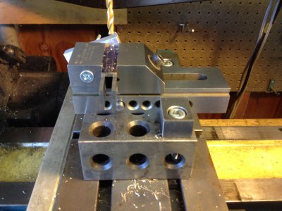
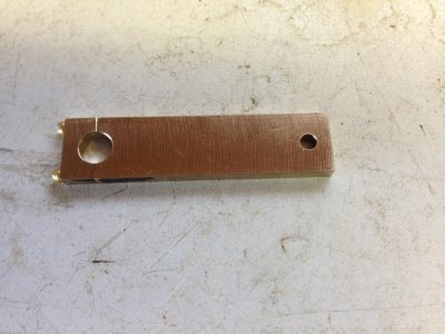
Next I moved over 1.625" and centerdrilled then drilled the #31 (.120") hole for the wrist pin and I chased a .126" reamer through that hole.
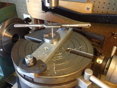
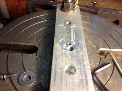
Above I have mounted my rotary table on the mill, set it to exactly zero degrees and located the exact center using the hole that is in the center of the table. I mounted a scrap piece of aluminum bar on the table and drilled a hole in the exact center so I could tap the hole with a 5-40 tap. The major diameter of a 5-40 screw is pretty close to .125" so it fits snuggly in the wrist pin hole.
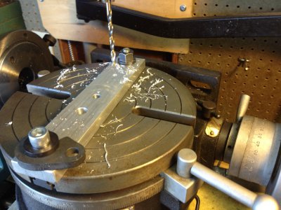
Above I moved over 1.625" and drilled a #7 hole so I could thread it with 1/4-20.
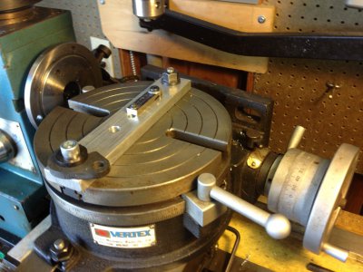
Now because I want two identical parts and I don't want to do this all day, I stack the two connecting rod blanks and screw them down to the aluminum bar mounted on the top of the rotary table. I had previously determined the angle of the taper using trigonometry to be 1.704 degrees.. Now I'm not kidding myself about accuracy so I moved the table 1 degree and 42 minutes (.704 = 70% of 60 minutes).
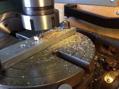
I put a 1/8" endmill and adaptor in the mill. I moved down until the endmill was cutting a little aluminum and then into the part about .025" and conventional milled along the side of the taper. I only fed in 25 thou because I don't want to break off the end of the end mill and I sure don't want to break the 5-40 screw. I climb milled back to the starting point with out advancing into the work for a nice finish. I made a couple .025" passes and then stopped to look.
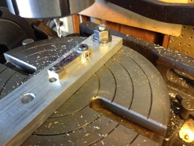
The line of the milling edge is parallel with the line I scribbed on the part, which is what I wanted to see.
So, went ahead and milled down to the line, so to speak.
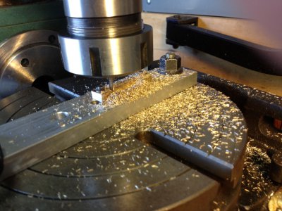
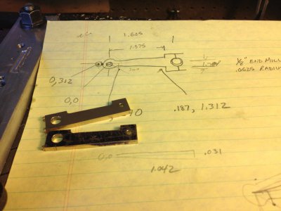
This is what the two parts looked like at this point. I want the other side to be a mirror image of the first, so I deburred the first side and then flipped the pair of parts over and bolted them back down on the bar upside down from the way they were the first pass.
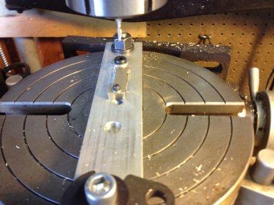
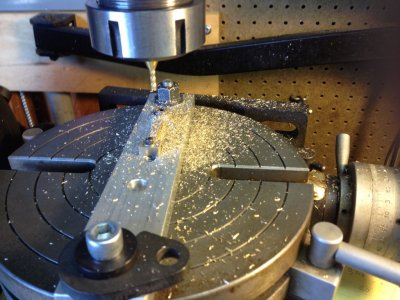
And cut the second side the same way I cut the first...
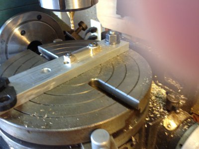
Now to cut the round head of the part around the wrist pin hole, all I had to do was slowly feed in about .025" each pass as I rotated the table around the center of the hole in the wrist pin, which again is the center of the rotary table. It was a sweep of about 300 degrees. I stopped when the endmill was half the diameter of the round head (.125") plus half the diameter of the endmill (.0625") equals .187" away from the center. Unfortunately, I forgot to take pictures of this process, my bad.
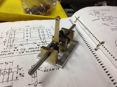
I deburred and cleaned up the shape a little with a file. Here is a couple pictures of the finished parts:
This is my first attempt at sharing something like this on this forum. I hope someone enjoys looking at the pictures and is able to take something away from this.
Dave
These machines are not dangerous unless you forget how really dangerous they are.


Sorry I didn't take photos of these first steps but, I had previously cut two pieces of bronze to size. I then drilled the holes for the little 1-78 screws more than 1/2 an inch deep and then I drilled the #49 clearance holes pretty much 1/4" deep. I then carefully tapped the 1-78 holes. Next I used a slitting saw to cut the 1/4" connecting rod cap off the rod. I put the cap back on the same way it was sawed off with the 1-78 screws. I stamped a small witness mark on each rod with cap so that I could reassemble them the exact same way everytime. I Dykemed one of the parts and scribed the location of the holes and the outline of the desired shape.
The photo below shows the blueprint for the parts and one of the two blanks for the connecting rods.


In the photo above I have mounted my vise on the mill and carefully dialed it in. Because I am making two parts and I want them the same, I have mounted a stop on the back side of the vise. I used a center drill to mark the spot of the large hole. I am about to drill through the part with a letter C drill (.242") because it is just a few thousandths smaller than 1/4" and I will chase a .251" reamer through the hole because the crank shaft journal is .250".

Next I moved over 1.625" and centerdrilled then drilled the #31 (.120") hole for the wrist pin and I chased a .126" reamer through that hole.


Above I have mounted my rotary table on the mill, set it to exactly zero degrees and located the exact center using the hole that is in the center of the table. I mounted a scrap piece of aluminum bar on the table and drilled a hole in the exact center so I could tap the hole with a 5-40 tap. The major diameter of a 5-40 screw is pretty close to .125" so it fits snuggly in the wrist pin hole.

Above I moved over 1.625" and drilled a #7 hole so I could thread it with 1/4-20.

Now because I want two identical parts and I don't want to do this all day, I stack the two connecting rod blanks and screw them down to the aluminum bar mounted on the top of the rotary table. I had previously determined the angle of the taper using trigonometry to be 1.704 degrees.. Now I'm not kidding myself about accuracy so I moved the table 1 degree and 42 minutes (.704 = 70% of 60 minutes).

I put a 1/8" endmill and adaptor in the mill. I moved down until the endmill was cutting a little aluminum and then into the part about .025" and conventional milled along the side of the taper. I only fed in 25 thou because I don't want to break off the end of the end mill and I sure don't want to break the 5-40 screw. I climb milled back to the starting point with out advancing into the work for a nice finish. I made a couple .025" passes and then stopped to look.

The line of the milling edge is parallel with the line I scribbed on the part, which is what I wanted to see.
So, went ahead and milled down to the line, so to speak.


This is what the two parts looked like at this point. I want the other side to be a mirror image of the first, so I deburred the first side and then flipped the pair of parts over and bolted them back down on the bar upside down from the way they were the first pass.


And cut the second side the same way I cut the first...

Now to cut the round head of the part around the wrist pin hole, all I had to do was slowly feed in about .025" each pass as I rotated the table around the center of the hole in the wrist pin, which again is the center of the rotary table. It was a sweep of about 300 degrees. I stopped when the endmill was half the diameter of the round head (.125") plus half the diameter of the endmill (.0625") equals .187" away from the center. Unfortunately, I forgot to take pictures of this process, my bad.
I deburred and cleaned up the shape a little with a file. Here is a couple pictures of the finished parts:


This is my first attempt at sharing something like this on this forum. I hope someone enjoys looking at the pictures and is able to take something away from this.
Dave
These machines are not dangerous unless you forget how really dangerous they are.


