- Joined
- Nov 14, 2016
- Messages
- 3,009
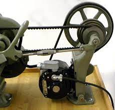
I've got a very nice Rivett 608 lathe, but it is missing the factory drive system. Rivett offered a variable speed underdrive or an overhead shaft drive. What I have is a homebuilt rear drive like you would find on an Atlas or South Bend benchtop lathe.
While not factory it was fairly well done except for the tension linkage which was literally just to jam a rod between the lathe and counter shaft assembly, this was clearly meant as a temporary solution for an unfinished project.
I have a complete counter shaft and linkage assembly from a South Bend 9 which I thought would work, but although this is an 8-1/2" lathe the SB set up is massive in comparison. It is also possible that although advertised as being from a SB9 it actually came from a larger lathe. It would take a great deal of work to make it work, requiring more than half the parts to be replaced, and would end up making the lathes footprint very deep.
Plan B is to reuse the existing countershaft but make my own linkage to lock it in place. Advantage is that it fits the lathe and has powered it before, it also results in a footprint at least a foot narrower that using the SB part.
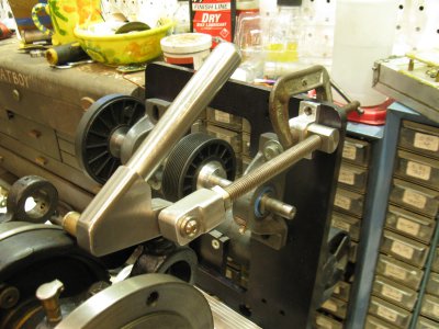
The tricky part is how to make the locking mechanism. There is no physical lock, these seem to rely on leverage, so that when pushed to lock position it holds, but when the lever is pulled back the "knee" breaks allowing the linkage to bend. I can not find anything explaining how the geometry works so that I might be able to make one.
Last resort would be to make some sort of twist lock, but if possible I'd really make something that just relies on the position of the lever.
I suppose I could use the one from the SB counter shaft, but I hate to cannibalize a complete unit for just the one part.
Has anyone ever made one of these or have a good idea how it is done?
Example of what I'm referring to, the lever and rod in the foreground. BTW looking at the photo I'm further convinced the unit I have came from something larger than a SB9.


