- Joined
- Aug 15, 2022
- Messages
- 8
Hello, just trying to dive in to all this and learning as I go. I'm a complete novice and have everything to learn.
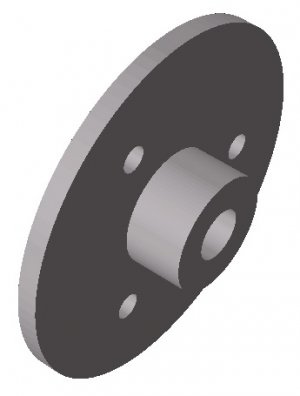
Anyway, as from my introduction post, I'm working on a project where I need to make an adapter. I was originally thinking of making the part from 6061-T651, and a slightly different overall design, but realized that I could simplify the part making it easier to machine and thinner (for space considerations) using steel. However, material selection is overwhelming to me at the moment and could use some input and guidance.
Looking at my 3D model below, the center hole will be tapped to a M12x1.5 internal thread. This part, when assembled, will be threaded on to a small crankshaft and torqued down to 47ft-lbs. My question, which steel would be the easiest to machine yet strong enough to hold that amount of torque on the threads? Would hot rolled A36 work for this or do I need to step up to something like 4140 or ??? The part is a non-wear piece other than installation and removal but can be spun up to 10,000 rpm and will be used to keep the much heavier flywheel in place when torqued down.


