-
Welcome back Guest! Did you know you can mentor other members here at H-M? If not, please check out our Relaunch of Hobby Machinist Mentoring Program!
You are using an out of date browser. It may not display this or other websites correctly.
You should upgrade or use an alternative browser.
You should upgrade or use an alternative browser.
Measurement Of Angular Surface
- Thread starter Swerdk
- Start date
- Joined
- Nov 10, 2013
- Messages
- 837
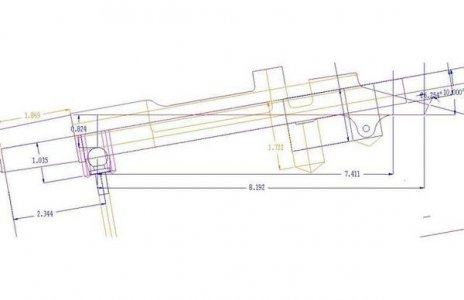
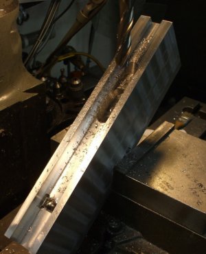
I use both ball bearings and cylindrical rods (gauge pins) to measure angle placement very often. One example would be making the female dovetail for a tool holder for a quick change tool post. You cut the dovetail with an dovetail cutter so how do you determine when the two angles are far enough apart without taking it out of the mill? You put a dowel pin into each side and measure the width between them calculated from the tangencies. Basically, you use it whenever there are angled surfaces involved and their placement is critical. I use CAD to get my dimensions though, it's faster for me than looking up the math equation. You can also use the ball bearings for machining cones to depth. (think heavy chamfers around the tops of holes).
- Joined
- Nov 10, 2013
- Messages
- 837
That is the standard and accepted method for angular measurement as for dovetails etc. I don't have my Machinery's Handbook handy right now but I'll bet it would give you a more understandable illustration.
Sent from my iPad using Tapatalk
Sent from my iPad using Tapatalk
- Joined
- Mar 19, 2014
- Messages
- 2,682
If you mean making a tool holder with the dovetail? I would use a premade cutter with the proper angle. And use two reference dowel pins and a dial caliper should be good enough to measure the dovetail opening. You will need to trig out the number, using the dowel diameter and angle…Dave.
- Joined
- Jan 22, 2011
- Messages
- 8,031
Copy an existing toolholder if you have one. Choose pins that contact approximately halfway up the angled surface. The pins, if you have a set of gage pins, can be 0.0010 apart, not that it makes any practical difference. If you use off the shelf dowel pins you should be safe.
- Joined
- Feb 1, 2015
- Messages
- 9,910
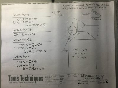
toms techniques website give a chart for measuring a angled surface with a cylindrical rod. I cant figure out how i would use this in machining? How do i apply it to making wedge inserts for phase II for instance. Am i off?
I have used ball bearings to specify/measure conical depressions, dowel pin pairs to measure taper angles and dovetail slot widths, and a similar device to the drawing for finding virtual edges.
However, I am not sure how this would be implemented either. The radius r is known, 1/2 the cylinder diameter. You can measure m, assuming the surface is perpendicular to vertical in the drawing. You need to know one more variable; either CH, CL or A. Measuring CH requires being able to locate the edge between the vertical and the taper, something that is hard to do accurately. Measuring CL requires locating the edge between the horizontal and the taper, again something that is hard to do accurately. You are presumably trying to find A. It is possible to determine the angle with a second cylinder of different size but because of the small difference I would not expect a high degree of accuracy.
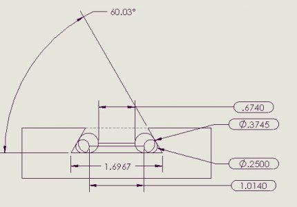
If you are trying to measure a dovetail slot as in a QC tool holder, it can be fully characterized by measurements with two sets of different diameter dowel pins. The two smaller dowel pins are laid in the opposite corners of the dovetail and the distance between them measured. Then the two larger dowel pins are laid in the corners and distance between them measured. The angle and the distance across the base of the dovetail can then be calculated with geometry and trigonometry. As Holescreek suggests, it is easier to use a CAD program to determine the unknown values. I measured my Shars tool holder using a pair of .250 and a pair of .3745 pins and drew up a CAD drawing based on the measurements. The circled dimensions are measured values. As you can see, the the dovetail angle anddovetail base width are both determined from the measurements made.
Bob
