Was it this backing plate?
 www.precisionmatthews.com
-
Welcome back Guest! Did you know you can mentor other members here at H-M? If not, please check out our Relaunch of Hobby Machinist Mentoring Program!
You are using an out of date browser. It may not display this or other websites correctly.
You should upgrade or use an alternative browser.
You should upgrade or use an alternative browser.
Metric or imperial lead screw on my 10 x 20 lathe
- Thread starter Laz
- Start date
- Joined
- Feb 1, 2015
- Messages
- 9,637
Thankks RJ.
I agree it is only similar to the Grizzly. I have checked the lead screw multiple ays and the screw appears to 12 TPI. This Lathe was probably intended for the European Marked. The Chuck system is one they use in Germany. I like it because it is not screw on. I found backing plate blanks at precision Mathews. One of their imports must use the same system.
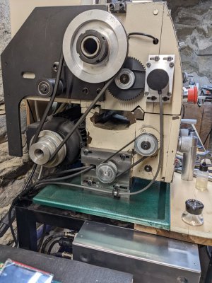
I have all the ELS parts now. It will take some time to figure out how to load the software etc. I use Apple, but James said it should not be a problem. The outer issue with this Late is the Idler arm for the pully belts is in a different place so I may have to mount the Servo meter outside .
Thanks again.
Mike
I finally got my head around your metric gear chart and the metric threads come out close but not exact. They re about .05% smaller than nominal. For most purposes, this is close enough.
I used a different scheme for mounting my stepper. I have a NEMA 24 hybrid stepper which fits neatly under my lathe ways. @WobblyHand used the same scheme for his ELS version. It is out of the way there. If the bed casting for your lathe is similar, that might be an option.
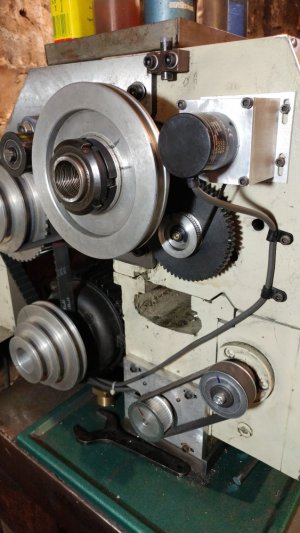
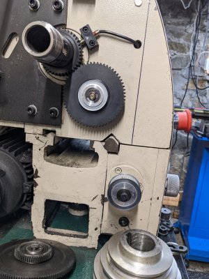
A photo of the back end of your lathe would help me visualize your layout. In particular, the G0602 uses a 40 tooth gear on the spindle driving a 60 tooth gear. I believe you have the same configuration but it is wise to check. I mounted the gearbelt pulley on the 60 tooth gearas did Clough. I am driving the lead screw gearbox input with a 1:1 ratio. and gearing down 2:1 with the gear box as I found the increased torque beneficial. If I were doing it again, I would use 2:1 gearbelt pulleys instead.. Here is a photo of my setup.

- Joined
- Dec 18, 2019
- Messages
- 6,478
Here's the location without the motor. Sorry about the crooked angle.I finally got my head around your metric gear chart and the metric threads come out close but not exact. They re about .05% smaller than nominal. For most purposes, this is close enough.
I used a different scheme for mounting my stepper. I have a NEMA 24 hybrid stepper which fits neatly under my lathe ways. @WobblyHand used the same scheme for his ELS version. It is out of the way there. If the bed casting for your lathe is similar, that might be an option.
A photo of the back end of your lathe would help me visualize your layout. In particular, the G0602 uses a 40 tooth gear on the spindle driving a 60 tooth gear. I believe you have the same configuration but it is wise to check. I mounted the gearbelt pulley on the 60 tooth gearas did Clough. I am driving the lead screw gearbox input with a 1:1 ratio. and gearing down 2:1 with the gear box as I found the increased torque beneficial. If I were doing it again, I would use 2:1 gearbelt pulleys instead.. Here is a photo of my setup.
View attachment 432028


I had to enlarge the rectangular opening with a die grinder, but there was plenty of room to fit a NEMA-24 stepper motor inside. Took off a little on the sides and about 1/4" along the top edge, so the 2.4" x 2.4" flange of the motor could clear the opening.
Here is a link to the thread i started for my ELS conversion:

 www.hobby-machinist.com
The PM 1022/1030 lathes have a whole in the casting where you can stuff the motors in there as does that series of Grizzly lathes but unfortunately the end of mine is solid. I assume that webbing adds some rigidity so i didn't feel comfortable cutting a big hole in it.

ELS Conversion on Weiss 1127
I have started the conversion of adding an ELS onto my lathe. Here are some pics of the progress: I'm happy with the stepper motor mount - it is very rigid. I plan on doing a bit more fit and finish on the stepper mount. The encoder mount i'm redoing b/c the bracket kicks slightly...
 www.hobby-machinist.com
The PM 1022/1030 lathes have a whole in the casting where you can stuff the motors in there as does that series of Grizzly lathes but unfortunately the end of mine is solid. I assume that webbing adds some rigidity so i didn't feel comfortable cutting a big hole in it.
- Joined
- Dec 18, 2019
- Messages
- 6,478
Grizzly didn't seem to think that a solid wall added much to the lathe. For myself, it was a bit of a pain to open up the hole. Using a file got me nowhere in a hurry. Ended up using an air die grinder and a carbide bur to open it up more. Grinding cast iron is messy.Here is a link to the thread i started for my ELS conversion:

ELS Conversion on Weiss 1127
I have started the conversion of adding an ELS onto my lathe. Here are some pics of the progress: I'm happy with the stepper motor mount - it is very rigid. I plan on doing a bit more fit and finish on the stepper mount. The encoder mount i'm redoing b/c the bracket kicks slightly...www.hobby-machinist.com
The PM 1022/1030 lathes have a whole in the casting where you can stuff the motors in there as does that series of Grizzly lathes but unfortunately the end of mine is solid. I assume that webbing adds some rigidity so i didn't feel comfortable cutting a big hole in it.
If faced with a closed end wall, I'd probably also be reticent about putting a 2.4 x 2.4" hole in it. On the other hand, it does seem to work well on my G0752Z/G0602. It gets the motor totally out of the way and makes the install quite compact. I have a tightly packed small shop, so any time I can reuse space, I take advantage of it.
Last edited:
Thanks for the photos. They really help. I pent way to much time trying to figure out the gear charts. I will just proceed. the 24 TP Lead screw and continue my ELS conversion. I am just finishing my VFD motor conversion. Worked well except for obtaining a 3 phase metric motor. It took several tries till I found one not damaged.
Her are some pictures of my motor mounting.
IT seems to run OK but for some reason I coot get the motor to run in the SLV mode. Parameter 00.00 on the VFD. when I switch to SLV. the motor will not run in reverse. My knowledge on how to set this up is based only on the Clough42 video on VFD conversion. There is some sort of Auto tune function , but n to sure what that does.
Nay help is appreciated.

