- Joined
- Oct 31, 2016
- Messages
- 2,645
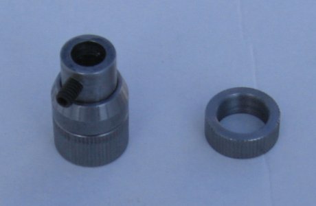
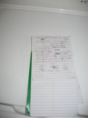
I decided to make one of these. Not hard to make. Just took a while. Whenever I start a project like this I do lots of research. Saw lots of these stops in videos but none gave much in the way of dimensions. Stumbled on Midway's description which provided enough info to figure the rest out. PTG Micrometer Adjustable Reamer Stop (midwayusa.com) I typically draw a 3d image of what I intend to make. I did a rough drawing. I also like to write out important info and keep it handy while I make something. I had a 1 1/8" 1018 round bar that I decided to use. Decided to make the base .750 OD and left the OD on the rings (wrong term?) at 1.125". Then ran 40 tpi threads through an online thread calculator to get the major, .7437 to .7488, and minor diameters, .7286 to .7326, and the measurement over wires. The calculator called for .0144 wires which I didn't have. Smallest of my wires was .018. Grabbed the Machinery's Handbook for the formula for the measurement over wires. Measurement over wires calc'd out at .7607.
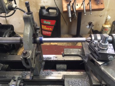
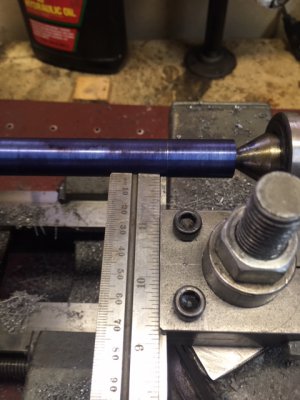
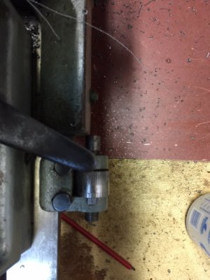
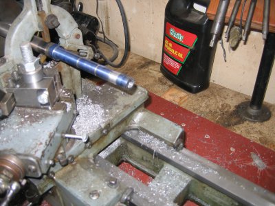
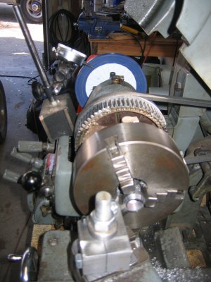
With a basic plan the first thing up was to turn one end of the bar down to .750 between centers for the bases. I used a steady rest to keep the bar from bowing while I turned enough of the bar for 5 bases. .750, 1.00, 1.25, 1.50, & 1.75 inches long. After turning I marked off the different base lengths one at a time including a groove to end the 40 tpi threads in and for parting off. Used the parting tool tool to make the grove. To square up the parting tool I placed a straight edge against. I didn't want a grove for the start of the threads. So I used the threading tool to cut a notch to start the threads in. I set a carriage stop for the starting point. This way I would always start the threads in the same spot in the groove. Because I was concerned about cutting the 40 tpi threads I decided to only make the 1.25 long base. Cut the threads with no problems. I used the thread gauge to check on my progress. 40 tpi is so fine that I had to use a magnifying glass to be able to see how the gauge fit in the threads. When I thought that I was done I used the wires to confirm. Calc'd measurement was .7507 and the threads mic'd at .7511. That was close enough. Trying to hold the tiny wires and get a mic was darn near impossible with the mic pointing up. Flipped the mic so it was pointing down, didn't have to hold it, and the weight of the mic was sufficient to hold two wires on top while I got the 3rd wire in place on the bottom. Next up was to bore the base for the reamer. I had a lot of stick out from the steady rest. The target ID was .473. A 15/32 drill is .46875. I started with a 1/4" drill and stepped up in 1/16" increments with the last step with the 15/32 drill. I will finish the bore with the reamer. Parted off this base and parted off the rest of turned down bases.
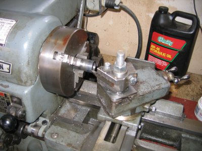
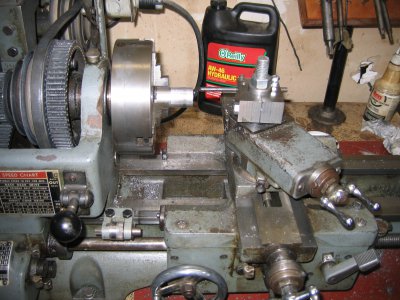
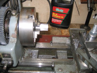
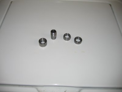
Next up was to make what I call the rings. I was going to do this in the steady. Then decided that it would be easier to make them in the 3 jaw. Over to the band saw and cut off enough material for the rings plus some extra. Back to the lathe. The target ID was .7286 to .7326. I shot for .730 and came in on the money. I bored all the way through. Step drilling first and then finishing with a boring bar. I decided to make the micrometer ring first. This ring was .375 long. Set the carriage stop at .500 and cut the thread until the base screwed in. I wanted the micrometer lines to be close to the lines on the base for easier reading. So I angled the edge of the ring at 70 degrees. I also needed to remove a portion of the threads so the ring would slip over the base. Should have done it now but didn't. Parted it off. Next was the two remaining rings. I made them as one ring. In hindsight I should have made them separately. After cutting the threads I scored the outside for better grip using the indexing feature on my lathe. This gave me 60 equally spaced lines around the outside. Parted off the shorter ring at .375" and the longer ring at .625". Here is why I should have made them separately. The shorter ring fit just fine on the base. But because of spring in cutting the threads the longer ring was a very tight fit. Had to use a wrench to screw it on and off several times before it became easy enough to screw on by hand. Part of the problem may have been that any little bit crud in the 40 tpi threads causes the rings and the base to lock up.
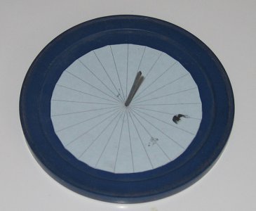
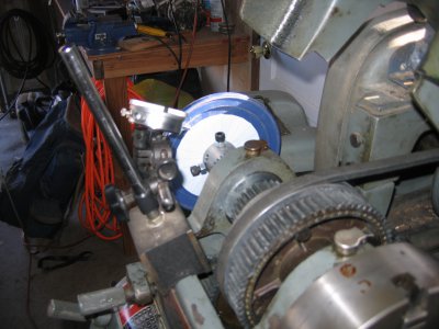
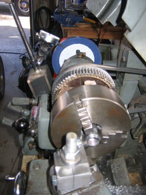
Last was to mark the mic ring with 25 lines. Was going to get a 100 tooth saw blade from Home Depot. Instead I divided a circle into 25 parts in sketchup and printed it out. Stuck a framing nail through the center and used a plastic lid for support. Put it in the spider I had recently made and with a DI as a pointer I was good to go. Marked the 4 lines on the base using the indexing feature on the lathe. Drilled and tapped for a set screw and it is done.

With a basic plan the first thing up was to turn one end of the bar down to .750 between centers for the bases. I used a steady rest to keep the bar from bowing while I turned enough of the bar for 5 bases. .750, 1.00, 1.25, 1.50, & 1.75 inches long. After turning I marked off the different base lengths one at a time including a groove to end the 40 tpi threads in and for parting off. Used the parting tool tool to make the grove. To square up the parting tool I placed a straight edge against. I didn't want a grove for the start of the threads. So I used the threading tool to cut a notch to start the threads in. I set a carriage stop for the starting point. This way I would always start the threads in the same spot in the groove. Because I was concerned about cutting the 40 tpi threads I decided to only make the 1.25 long base. Cut the threads with no problems. I used the thread gauge to check on my progress. 40 tpi is so fine that I had to use a magnifying glass to be able to see how the gauge fit in the threads. When I thought that I was done I used the wires to confirm. Calc'd measurement was .7507 and the threads mic'd at .7511. That was close enough. Trying to hold the tiny wires and get a mic was darn near impossible with the mic pointing up. Flipped the mic so it was pointing down, didn't have to hold it, and the weight of the mic was sufficient to hold two wires on top while I got the 3rd wire in place on the bottom. Next up was to bore the base for the reamer. I had a lot of stick out from the steady rest. The target ID was .473. A 15/32 drill is .46875. I started with a 1/4" drill and stepped up in 1/16" increments with the last step with the 15/32 drill. I will finish the bore with the reamer. Parted off this base and parted off the rest of turned down bases.


Next up was to make what I call the rings. I was going to do this in the steady. Then decided that it would be easier to make them in the 3 jaw. Over to the band saw and cut off enough material for the rings plus some extra. Back to the lathe. The target ID was .7286 to .7326. I shot for .730 and came in on the money. I bored all the way through. Step drilling first and then finishing with a boring bar. I decided to make the micrometer ring first. This ring was .375 long. Set the carriage stop at .500 and cut the thread until the base screwed in. I wanted the micrometer lines to be close to the lines on the base for easier reading. So I angled the edge of the ring at 70 degrees. I also needed to remove a portion of the threads so the ring would slip over the base. Should have done it now but didn't. Parted it off. Next was the two remaining rings. I made them as one ring. In hindsight I should have made them separately. After cutting the threads I scored the outside for better grip using the indexing feature on my lathe. This gave me 60 equally spaced lines around the outside. Parted off the shorter ring at .375" and the longer ring at .625". Here is why I should have made them separately. The shorter ring fit just fine on the base. But because of spring in cutting the threads the longer ring was a very tight fit. Had to use a wrench to screw it on and off several times before it became easy enough to screw on by hand. Part of the problem may have been that any little bit crud in the 40 tpi threads causes the rings and the base to lock up.


Last was to mark the mic ring with 25 lines. Was going to get a 100 tooth saw blade from Home Depot. Instead I divided a circle into 25 parts in sketchup and printed it out. Stuck a framing nail through the center and used a plastic lid for support. Put it in the spider I had recently made and with a DI as a pointer I was good to go. Marked the 4 lines on the base using the indexing feature on the lathe. Drilled and tapped for a set screw and it is done.


