Mike's 6-Axis Articulated Robot

Attached the PDF manual that I received from DENSO. Had to compress it and split into 6 parts to fall within H-M's limit of 4MB per attachment.
 

Attachments

  • VS-C_(A)_(E) Reduced_Part1.pdf
    4 MB · Views: 9
  • VS-C_(A)_(E) Reduced_Part2.pdf
    4 MB · Views: 1
  • VS-C_(A)_(E) Reduced_Part3.pdf
    4 MB · Views: 0
  • VS-C_(A)_(E) Reduced_Part4.pdf
    4 MB · Views: 2
  • VS-C_(A)_(E) Reduced_Part5.pdf
    4 MB · Views: 0
  • VS-C_(A)_(E) Reduced_Part6.pdf
    3 MB · Views: 0
I love reverse engineering old stuff and getting it working.
wow, proves my theory that there is someone for every imaginable task. I'm not an electronics guy so it's a no go for me. But to incorporate a smaller arm into my process is a long wished dream. I'm watching the prices of those small robot arms come down with interest.
 
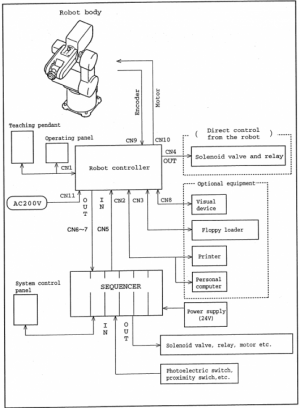
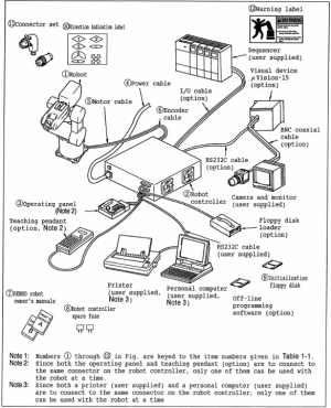
Here is an overview of the system as DENSO intended.

1643643082872.png
1643645083595.png

The required components are
  1. Robot - Have it!
  2. Robot Controller - Have it!
  3. Operating Panel - Missing ($250 on ebay). From tables in the manual, the teach pendant covers all the functions of the operator panel.
  4. Power Cable - Missing, unknown part #.
  5. Robot power cable - Missing, unknown part #
  6. Robot encoder cable - Missing, unknown part #
  7. Manuals - I have the important one, missing the programming manual
  8. Spare Fuses - Missing, not important, easy to replace
  9. Initialization Floppy Disks - Have the WinCAPS software thanks to DENSO (runs on Win95 or Win98). Missing disk 2, calibration data
The optional components are:
  1. IO cables, (1) Digital Input, (1) Valve Control, (2) Digital Output, all missing, some available on eBay for (~$150 each)
  2. Teach Pendant - Have it!
  3. Teach Pendant Cable - Missing
  4. Extension cables - Don't need them.
  5. Cooling Fan system for controller - Don't need it
  6. Floppy Disk Drive - Needed to load calibration data and offline programs
  7. WinCAPS software - Have it!
  8. Data Disk for specific robot to enable with WinCAPS - Missing

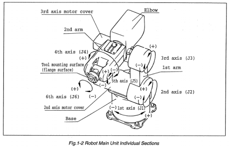
Here is a nice illustration of the robot's main components:

1643643648108.png

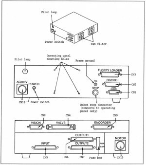
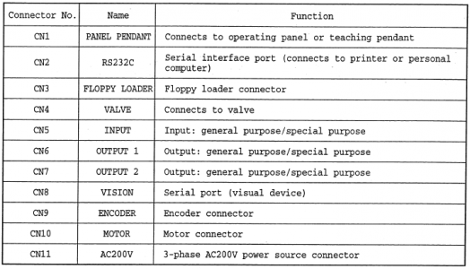
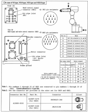
Pictures of the controller connections:

1643643680255.png
1643643699214.png

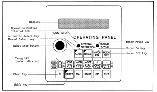
A drawing of the Operating Panel (which I don't currently have):

1643643740639.png

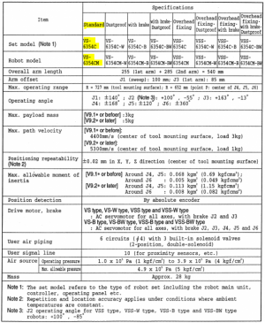
And the specifications for my model of robot (highlighted in Yellow):

1643643807388.png

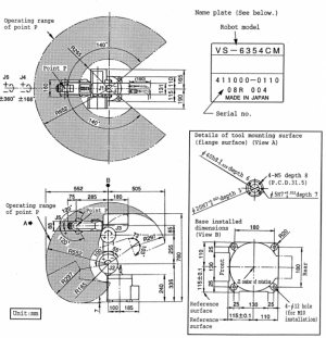
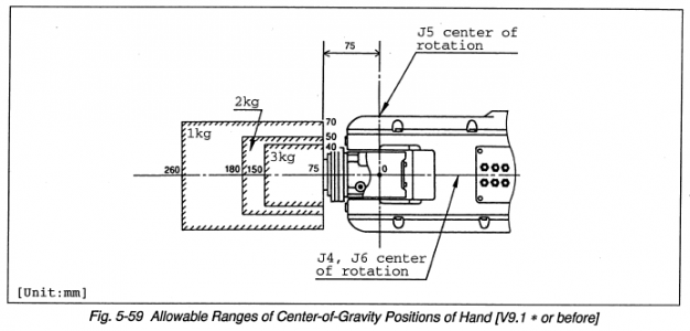
A nice drawing of this robot's working area:

1643643842258.png
1643645270773.png

Graphic of robot connections:

1643643917678.png

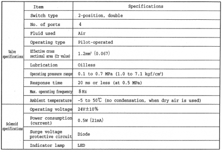
Built in solenoid valve specifications:

1643643967578.png

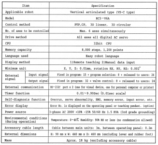
And controller specifications:

1643643997957.png
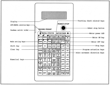
And the teach pendant drawing:

1643644156107.png

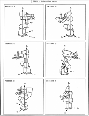
Will have to dive into a lot more detail in a later post, but here are the 6 possible poses with this robot.

1643644749981.png

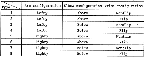
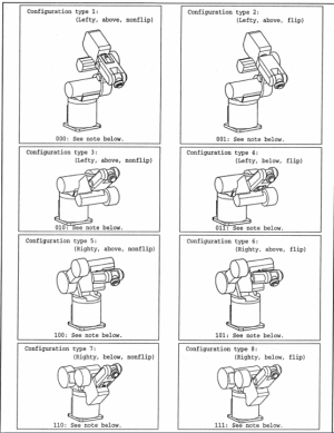
And all 8 possible poses. Some are unreachable due to mechanical limitations of this robot.

1643644847312.png

1643644897606.png
 
Looks like you got lucky with someone at DENSO willing to share some things. Would be nice to find the programming manual. Hopefully the missing cables are something you can find the right pin-outs for and just make up yourself.
 
So I hinted at this in my earlier posts, but I have 4 options to get this running:
  1. Get all the required components for this robot's original system and run it as the manuals entail.
  2. Scrap the original controller and run the robot on Allen Bradley PLC and servos. This is how I got my other robot running.
    1. Kinetix 2000 (which I have) or Kinetix 5300 (which I don't have) servo drives *might* be able to run the motors without any changes (compatible feedback).
    2. A feedback converter board may allow me to run these motors with any servo drive (difficult task, only if absolutely necessary).
  3. Find servo drives which are compatible with the feedback from the motors and can use Step/Dir commands. Run on LinuxCNC on a PC.
  4. Find servo drives which are compatible with the feedback from the motors use Robot Operating System on a PC.
I'm leaning towards #2 since I could use a unified program to run either of my robots (or run them together), but perhaps I could find what I need to try either #1 or #2.
 
Looks like you got lucky with someone at DENSO willing to share some things. Would be nice to find the programming manual. Hopefully the missing cables are something you can find the right pin-outs for and just make up yourself.
Yes, they were very helpful so far. Adamant that they wouldn't provide support but definitely got me going with manuals and software. I have a ton of questions to ask them, so I need to order them in order of most to least important. Maybe I can get a few more answered before they block my phone #!

I expect I'll need info from DENSO, Panasonic, and Tamagawa (makes motor encoders).
 
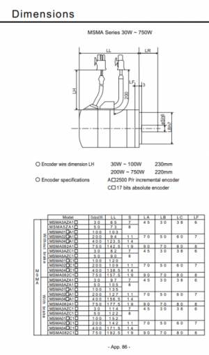
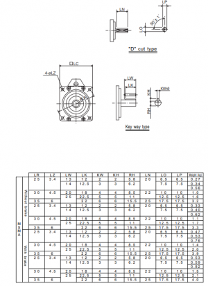
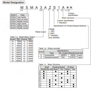
Here is a snip from a Panasonic Minas A1 and A3 manuals (attached). The part numbers are not quite right, but they are close. Even if DENSO has some special options added, the motor electrical parameters would most likely match the off the shelf motors from Panasonic.

Here is the J6 motor for example: MSM5AZQ6Q

I'm guessing, low inertia (MSM vs MSMA, probably the same thing), 50W, 100/200V. Q6Q is likely: Custom Encoder, Custom Motor Specification, Custom Motor Structure.


1643657526185.png

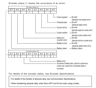
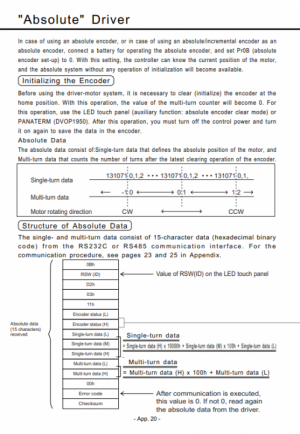
Additionally, the Panasonic manual has the best description of the serial packet framing of the encoder I have seen yet.

1643657851654.png
1643657876526.png

1643658012604.png
1643658101084.png

Also found an old MSMA manual containing just a bit of the motor data I need. Attached.
 

Attachments

  • minas_a_e.pdf
    1.8 MB · Views: 0
  • Panasonic-MSMA-User-manual.pdf
    1.2 MB · Views: 1
Went back an edited some earlier posts. Apparently the J2 and J3 motors have electromagnetic holding brakes which lock the motor when power is removed. The manual clearly showed this, but I missed it. These brakes keep the robot from falling over when power is removed.

This explains why I was unable to move J2 at all and why J3 was so difficult to move by hand. It is bad for the brakes to force them to move while engaged, so I'm going to cross my fingers that I did not do damage.

There was an option for this robot to have brakes on all axes, but this does not have that option. I guess I assumed that since mine didn't have them on all joints, then it didn't have them on any.

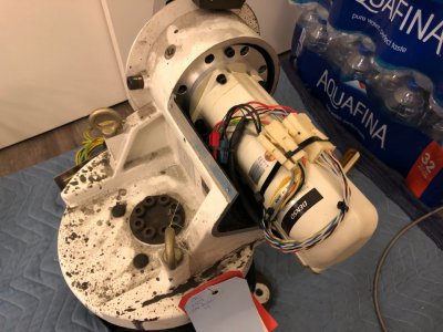
Notice the 3 connectors on the J2 motor below. The big one on the far right is the encoder, the 4 pin one in the middle is the motor power + GND, and the 2 pin one on the left is the brake. The red 2 pin connector, tucked along the side of the motor, is the place to short out the encoder when the robot is in the CALSET (calibration set) position to zero the encoder counts. This is necessary if the robot has crashed, gone too fast, or the batteries backing up the encoder data have died.

image011.jpg
 
Mike,
Not on your "what to do with the robot" list, but you keep showing soft drinks and bottled water in the background, so I've got to think you're going for the robotic bartender :)
 
Back
Top