Mike's SCARA Robot

I've ALWAYS been impressed with the ability of robot controllers to do the coordinate conversions required for cartesian motions and linear (or other path) interpolations - in real time!!! It really illustrates the computation speed of computers (even the ones 20 years ago, when your robot was built). As with others, I've been "lightly" following your fascinating build, but you've definitely left ne in the dust with respect to many of the details.

Congratulations on the first functional test!

It really amazes me that this can be done. I have to imagine the first guys trying to make robots work would have run into the difficulty of the task and I cant believe they didn't say this was more effort than it is worth.

I'm standing on the shoulders of giants here. Someone has pretty much done all the work of the inverse kinematics for me in the PLC. Granted it all needs to be set up correctly and I need to write a program to tell it what to do, but still all of the "hard" stuff is done behind the scenes. I tried learning all the math on my own about two years ago. I got through deriving the kinematic equations and the multiple inverse kinematic solutions, but that only tells you what position to move the joints to give a specific XY position. Beyond that, velocity and acceleration control, the actual path planning, etc. was beyond me.

I always picked on my computer science buddies in college ( I did Mech E. and EE) for having to take linear algebra, but now I do regret not taking it. The math for robots is laid out in matrices and I would have had a much easier time with the math if I had formally learned it.

Not sure if I mentioned it earlier, but if anyone comes along this thread and is really interested in robotics, the textbook "Introduction to Robotics: Mechanics and Control" by John J. Craig is excellent. It gently introduces you to the subject in the first few chapters with some simple robot configurations and basic math. By chapter 4, you are solving full kinematic solutions to robots (I spent nearly 3 months getting through that chapter). It goes on to cover Jacobians (velocities in robots), trajectory generation, singularity avoidance, linear and non linear control of an actuator, force control of a robot, and some robot programming (which I expect to be a bit out of date for modern robots). I really wanted to finish this book but lost focus since I didn't have a real robot to mess with yet. I would enjoy jumping back into it if I ever find myself with free time (haha).

 
I changed my program back to V33 using the kinematics with orientation control. Ran into a few issues along the way but ended up being successful. Below is a video showing the transform maintaining the angular position of the U axis (Look at the tape flag at the top of the white "tool"). This requires coordination of all 4 motors simultaneously. In the software I am only commanding a motion along the virtual cartesian X axis, the transform is doing the rest.


I have also modified the program to only require the robot to home after a power cycle. If the robot has been homed already the motors just turn on since they already know their absolute position. Additionally, the kinematic transform is kept active even when the motors are disabled. The transform automatically switches into "forward mode" and calculates the XYZU positions based on the joint motor angles. I can manually push the robot around and the transform updates the on-screen displays to show me the cartesian position.
 
Here is a simple program showing the robot executing a joint flip:


The kinematic transform cannot support this transition natively. Doing so would require it to approach the workspace boundary which is a mathematically undefined region which calculates infinite joint velocities. In this video, cartesian motion is programmed to approach very near the workspace boundary, then a set of synchronized moves are executed on the joints to re-orient them in the desired position, then cartesian moves may again be programmed without ever disabling the kinematic transform. The transition is accomplished with constant joint velocities rather than constant cartesian velocity.

In the final version of my software, I hope to have this process automated where I can define a vector along which to generate the joint flip, and all the motion and velocities required to make it happen are calculated automatically.

Orientation is not controlled through the flip, giving the incorrect orientation in the "lefty" configuration after the flip. I still need to figure out how to transition to a new orientation, but it shouldn't be too hard.
 
After a very long hiatus from this project, I got a kick to pick it up again. I'm stationed up in Alaska for work for a month and the sun barely sets so I have a bit of free time to work on the code side of this project while my shop is 4000 miles away.

I'll share the progress I make here, but I do want to clarify that I am not a programmer by trade so there are likely plenty of things I am going to do in a sub-optimal way. Also, I will be programming this on an Allen-Bradley ControlLogix PLC since it has some powerful real-time motion control built in that I am already leveraging for control of the robot. This makes the robot integration easy but takes away most of the nice programming constructs you have with C++, python, or any other computer programming language.

I have shared some fancy code architectures in the past, but I decided I wanted to start somewhat simple and work on the G-code parser and interpreter. The function will take a command bit, read one line of G-code, parse it into a data structure, and return. Once the data structure is filled, the motion planner will take over and execute the functions intended by the line of code.

Here is where I have gotten so far:

Code:
Err := 0;
ExErr := 0;
k := 0;
l := 0;

COP(SampleCode[0],WorkingString,1); //Copy G-Code to Working Tag
FOR i := 0 to WorkingString.LEN by 1 do; //Remove all Spaces
    FIND(WorkingString,SpaceCharacter,1,Location);
    if Location <> 0 then
        DELETE(WorkingString,1,Location,WorkingString);
    else
        exit;
    end_if;
end_for;

UPPER(WorkingString,WorkingString); //Capitalize all characters

if (WorkingString.DATA[0] < 65) OR (WorkingString.DATA[0] > 90) then // Check if first character is a letter, if not, set error
    Err := 1;
    ExErr := 1;
end_if;

while (WorkingString.LEN >0) do //loop through the entire working string and pull out all the key-value pairs and place them in the key-value array
    for j := 1 to WorkingString.LEN by 1 do    ; //Search for the next key character
        if (WorkingString.DATA[j] >= 65) AND (WorkingString.DATA[j] <=90) then
            NextKey := j;
            exit;
        end_if;
    NextKey := WorkingString.LEN;
    end_for;
    Mid(WorkingString,1,1,Key[k]); //Copy Code at index 1 into key array
    l := NextKey - 1;
    Mid(WorkingString,l,2,Value[k]); //Copy code between index 2 to the next letter into value array
    STOR(Value[k],RealValue[k]); //Convert the array of values to REALS
    k := k + 1;
    DELETE(WorkingString,NextKey,1,WorkingString);
end_while;

The code does the following functions:
  1. Copies a line of code from the program file to working memory
  2. Delete all spaces from the string
  3. Capitalize all the letters
  4. Pull out all the letter(key)-value pairs and store them in an array
  5. Convert all the values from string to floating point REAL datatypes
The language is a Rockwell Automation PLC programming language called Structured Text. Most PLC code is programmed in Ladder Logic, which I will be using for 90% of this program, especially the motion control, however Structured Text is excellent at array manipulation and loops which I need for the parser.

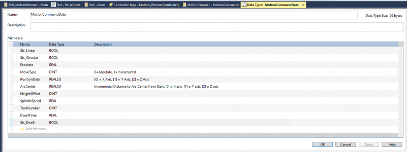
The data is stored in a User-Defined DataType (UDT) which I can create with all the structures necessary to store the parsed data. I am still in the early stages of figuring out what is needed, but here is what mine looks like so far.

1623819145963.png

Once the data is sorted into matching Key and Value arrays, I will have a second half of the parser place the data into the correct spots in the UDT, as well as particular global variables as needed. I've really only roughed the comments for this part but this is somewhat how it will look:

Code:
//-------------------------------------------------------------------------------------------------------
//------------------Code Parser---------------------------------------------------------------------
WorkingMotionData.Feedrate := Val_Feedrate;

For n:= 0 to 40 by 1 do
    case Key[n].DATA[0] of
        65: //A
            // No function coded at this time
            // A is reserved for motion about a rotary axis aligned along the X axis
        66: //B
            // No function coded at this time
            // B is reserved for motion about a rotary axis aligned along the Y axis
        67: //C
            // No function coded at this time
            // C is reserved for motion about a rotary axis aligned along the Z axis
            // Note that for the SCARA robot, U is used for rotary about Z axis
        68: //D
            // No function coded at this time
        69: //E
            // No function coded at this time
        70: //F
            Val_Feedrate := RealValue[n];
            WorkingMotionData.Feedrate := Val_Feedrate;
        71: //G
            case RealValue[n] of
                0:
                    //Move Rapid rate into feedrate
                    //Linear Interpolation
                1:
                    //Move Feed rate into feedrate
                    //Linear Interpolation
                2:
                    //Set circular interpolation CW
                3:
                    //Set circular interpolation CCW
                4:
                    WorkingMotionData.Sts_Dwell := 1;
                5:
                    //High performance look-ahead milling - not implemented
                6:
                    //Rational B Spline Machining
                7:
                    //Imaginary Axis Designation
                9:
                    //Exact Stop Termination
                10:
                    //Programmable Data Input
                11:
                    //Data Write Cancel
                12:
                    //Full Circle Interpolation CW
                13:
                    //Full Circle Interpolation CCW
                17:
                    //XY Plane Selection
                18:
                    //ZX Plane Selection
                19:
                    //YZ Plane Selection
                20:
                    //Set units to inches
                21:
                    //Set units to mm
                28:
                    //Return to home position
                30:
                    //Return to secondary home position
                31:
                    //Skip Cycle
                32:
                    //Long hand single point threading
                33:
                    //Constant Pitch Threading
                34:
                    //Variable Pitch Threading
                40:
                    //Tool Radius Compensation OFF
                41:
                    //Tool Radius Compensation Left
                42:
                    //Tool Radius Compensation Right
                43:
                    //Tool Height Offset (Negative)
                44:
                    //Tool Height Offset (Positive)
                45:
                    //Axis Offset Single Increase
                46:
                    //Axis Offset Single Decrease
                47:
                    //Axis Offset Double Increase
                48:
                    //Axis Offset Double Decrease
                49:
                    //Tool Height Offset Cancel
                50:
                    //Set Maximum Spindle Speed (CSS)
                    //Cancel Scaling
                52:
                    //Local Coordinate System (LCS)
                53:
                    //Machine Coordinate System
                54:
                    //WCS 1
                55:
                    //WCS 2
                56:
                    //WCS 3
                57:
                    //WCS 4
                58:
                    //WCS 5
                59:
                    //WCS 6
                54.1:
                    //Extended WCS (Requires P1-48)
                70:
                    //Canned Cycle
                71:
                    //Canned Cycle
                72:
                    //Canned Cycle
                73:
                    //Chip Break Canned Cycle
                74:
                    //Tapping Canned Cycle (LH)
                76:
                    //Fine Boring Canned Cycle
                80:
                    //Canned Cycle Cancel
                81:
                    //Simple Drilling Canned Cycle
                82:
                    //Drilling with Dwell Canned Cycle
                83:
                    //Peck Drilling Canned Cycle
                84:
                    //Tapping Canned Cycle (RH)
                90:
                    //Absolute Coordinate System
                91:
                    //Incremental Coordinate System
                92:
                    //Position Register
                94:
                    //Feedrate Per Minute
                95:
                    //Feedrate Per Revolution
                96:
                    //Constant Surface Speed (CSS)
                97:
                    //Constant Spindle Speed (RPM)
                98:
                    //Return to initial Z level in canned cycle
                99:
                    //Return to R level in canned cycle
            end_case;                 
        72: //H
            WorkingMotionData.HeightOffset := RealValue[n];
        73: //I
            WorkingMotionData.ArcCenter[0] := RealValue[n];
        74: //J
            WorkingMotionData.ArcCenter[1] := RealValue[n];
        75: //K
            WorkingMotionData.ArcCenter[2] := RealValue[n];
        76: //L
            // No function coded at this time
            // L contains the number of times to repeat a subroutine/canned cycle
        77: //M
            // No function coded at this time
        78: //N
            // No function coded at this time
            // N typically is coded for a line number and should not cause a control function
        79: //O
            // No function coded at this time
            // O is typically coded for the program number
        80: //P
            WorkingMotionData.DwellTime := RealValue[n];
        81: //Q
            // No function coded at this time
            // Q is the depth of peck in a canned cycle
        82: //R
            // No function coded at this time
            // R is the retract height in a canned cycle
        83: //S
            WorkingMotionData.SpindleSpeed := RealValue[n];
        84: //T
            WorkingMotionData.ToolNumber := RealValue[n];
        85: //U
            // No Function coded at this time
            // U should be the rotary motion about the Z axis
        86: //V
            // No Function coded at this time
            // V is an auxillary axis
        87: //W
            // No Function coded at this time
            // W is an auxillary axis
        88: //X
            WorkingMotionData.PositionData[0] := RealValue[n];
        89: //Y
            WorkingMotionData.PositionData[1] := RealValue[n];
        90: //Z
            WorkingMotionData.PositionData[2] := RealValue[n];
    end_case;
    if (Key[n+1].LEN = 0) then
        Exit; //At then end of the data in Key, exit the loop early
    end_if; 
End_for;

Once I get this working, I'll need to optimize it for scan time. The controller will only have a look-ahead of one block, so lots of extremely short moves will race against the processing time to parse and prepare the next move. The motion controller should be able to keep up a 2ms position command refresh no problem.

More to come - Mike
 
Well, here it is 7 months later and I really haven't made any progress forward. Life got immensely busy and I haven't had a chance to catch my breath. Wife and I moved from Cleveland to Detroit and are getting settled in our first owned home!

I left off on this project feeling a bit overwhelmed by the programming task in front of me. The robot and kinematics work perfectly, however I am limited to programming, in PLC ladder logic, a fixed operation for the robot. This is perfect for a defined task (like a robotic tool changer for my CNC mill), however it greatly lacks flexibility and ease of programming. For this reason, I really want to be able to have the robot run on G-code. Doing so allows rapid programming and availability to use graphical CAD/CAM programs to generate robot motion (rather than moving a cutting tool). There are low cost hobby programs which do this (Mach 3/4, LinuxCNC, GRRBL, etc.) but they lack the kinematics for the robot (well, it is possible in LinuxCNC, but that's a bit more complicated). So, to get the robot running on G-Code, I needed to essentially write these programs from scratch in PLC logic. I have actually done something very similar before (sadly I don't have the code) but it is a monumental task and there are a ton of gotchas which I have never found a good workaround for (like copying a text G-code file from a flashdrive to the PLC). I got a start on this task in June 2021 but stalled out.

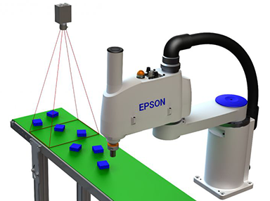
I was helping a buddy set up his first CNC machine and I had a lightbulb moment! The Rockwell PLC, once kinematics are active, allows you to electronically *gear* the robot's motion (in a cartesian axis) to an external encoder input. This is a common application for conveyor belt integration. The robot uses a camera system to locate a part on the conveyor, moves to the desired pickup location, then matches belt speed and direction during pick-up of the product. An encoder on the conveyor constantly streams position/velocity data about the conveyor to the PLC so that the robot matches the product motion exactly, even if the conveyor changes speed.

Check out this video at the 1:00-1:20 mark.

1643048883363.png

1643049486264.png

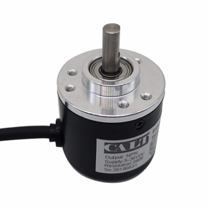
OK, well why do I care? Well it gets better. Not only can the PLC track one encoder, but it can track one encoder per cartesian and ancillary (rotation) axis all at the same time. In my SCARA robot with 4 degrees of freedom, this would be XYZ and U (rotation about Z). In a 6 axis robot you would have XYZUVW. And rather than commanding robot velocity as in a conveyor application, then encoders technically command position as one encoder pulse equates to a discrete step in distance or angle of rotation. OK cool. So I can have 4 encoders to command the robot around in 3D space. The encoders command cartesian positions and the PLC continues to handle the kinematics to generate the joint motion that places the end of the robot in the desired 3D space.

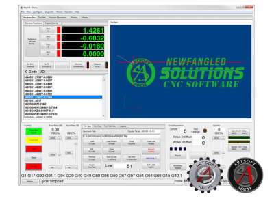
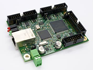
Well here is the lightbulb moment. The coordination of the 4-6 encoder signals that I want is exactly what all these CNC control programs (like Mach 4) do. So forget about all that custom programming of the G-code interpreter into the PLC, I'll do all that on a computer running software designed to do it. The software will send commands to a motion control board which will produce output command signals that look exactly like encoders to the PLC. My motion control board of choice, the Warp9 Ethernet Smoothstepper (used on my CNC mill) gives you the option to output step/direction pulses for stepper drives, or quadrature signals that look like encoders. The PLC is still handling the kinematics, so Mach 4 thinks it is commanded any normal CNC milling machine.

1643053773296.png

1643049414373.png

So in summary, Mach 4 handles reading G-code, motion planning, and axis coordination. The motion controller connected to Mach 4 generates signals for each axis that look like encoders. The PLC reads these encoders and blindly follows where they command the robot to go. The PLC converts cartesian (XYZ) coordinates to robot joint coordinates. And finally the PLC commands the servo drives to move the robot.

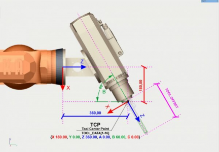
The PLC will need to handle functions like homing the robot and there will need to be some IO and communications between Mach 4 and the PLC (potentially digital IO for critical signals and Modbus for diagnostic data), but that is doable. Work offsets would be accounted for in Mach 4, but tool offsets (due to the nature of how they affect the kinematics) must be handled by the PLC.

1643049840717.png

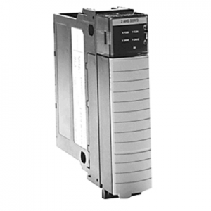
In order to read the (4) encoder inputs, I'll need (2) more dual channel analog servo cards (1756-M02AE). Each of these allows you to read (2) feedback only encoder axes. Remember, I'm already using (2) of these cards to command servo motion on the (4) robot joints. These are expensive modules, retailing at over $3000 each, but due to their age and the obscurity of their applications in modern motion control, there are literally hundreds of them on ebay, many selling in the $30 range.

1643049961653.png

I have some additional robotics related news that is a secret for now, but stay tuned!

Whooooo! I am excited about this again!
 
Last edited:
I'm going to put some info here, mostly for my own good about connector kits and other parts I'll want to update the wiring on this robot. When I was prototyping on this system, I hand wired lots of D-Sub connectors for attaching to the servo drives. Going forward, I'd like to start replacing those with purpose built cable sets using crimped D-Sub connectors. I think I will also build a custom PCB for the robot SIGNAL cable (MDR-68 connector) rather than having a ton of wires going all over the place. I'll also need to build a purpose built daughter board for the Ethernet Smoothstepper with optical isolation up to 4MHz for the encoders, and some cheaper ones for the general purpose IO.

DB-15HD
Plug Body: 180-015-173L000 (LINK)
Pins: 180-001-170L001 (LINK)
Backshell: 977-009-020R121 (LINK)

DB-44HD
Plug Body: 180-044-173L000 (LINK)
Pins: 180-001-170L001 (LINK)
Backshell: 977-025-020R121 (LINK)

MDR-68 Socket, PCB pins
Socket: DX20A-68S(50) (LINK)

PCB Terminal Blocks, Removable, Screw Clamp, 4 position example
Receptacle, 90 Deg.: TBP02R1W-381-04BE (LINK)
Receptacle, 0 Deg: TBP02R2W-381-04BE (LINK)
Plug: TBP02P1W-381-04BE (LINK)

Optoisolator, 1 Channel, High Speed (5Mbps), 5V
Optoisolator: TLP2395(TPL,E (LINK)

Cheap crimper that claims to do D-Sub: LINK
 
I have some additional robotics related news that is a secret for now, but stay tuned!
Alright I didn't want to jinx it before I knew I had won the purchase, but I got another robot! This is a 6 axis unit. I expect the project to follow the same path as this one did, but much of what I did to make this one work won't apply to the new one unfortunately.

Feel free to follow along if you'd like: https://www.hobby-machinist.com/threads/mikes-6-axis-articulated-robot.97888/

I plan on working on them concurrently as getting this one running on G-Code will also help the next one.
 
Bit distracted since I have a second robot now, but I did get 2 more analog modules in the mail. I really want to try hooking them up to a smoothstepper and letting it run. I just need a second Smoothstepper now.

As I've started learning about the 6 axis robot, I've learned that they are not really suited for control by Mach 4. The issue is that there are many places within its workspace volume that it cannot go, or had limited articulation within. If you try to control the robot in XYZ space, you'll find you can't move far before running into a limitation of articulation and the robot will fault out. Most sources I've seen recommend doing all the moves in joint space, where mathematical limitations don't apply, and saving the cartesian moves for the final approach to your target position.

The SCARA on the other hand doesn't suffer from this (other than the joint flip). As a result, it should be perfect to run G-Code, as long as it falls within the workspace of the robot and does not require a joint flip.

Haven't forgotten about this project.
 
Back
Top