Mill vise jaw clamp/stop.......

brino

Confirmed Tool User
H-M Lifetime Diamond Member
Joined
Jan 2, 2014
Messages
8,854
A few years back I picked up this 6" milling vise.

vise1.jpg

vise2.jpg

vise3.jpg

(.........and NO the battle scars were not caused by me, I got it used!)

I have wanted to build a jaw clamp and stop system that would allow removing the work-piece and putting it back in the same place.
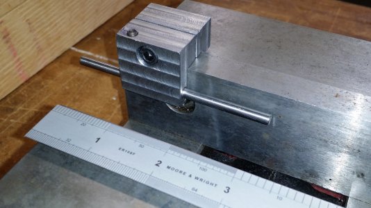
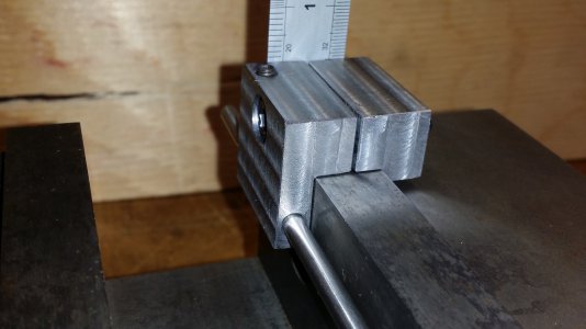
Each jaw is just over 1/8" above the vise body.

I looked at a few different designs and builds and then came up with this.

full.jpg

It is made from 1" x 2" hot rolled steel.
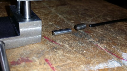
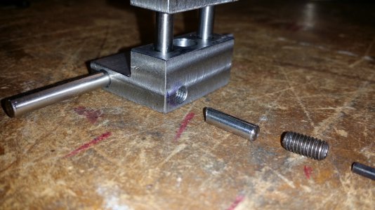
I used 3/16" dowel pins for the sliders, a 1/4"-20 Socket-Head Cap Screw (SHCS) for the clamp bolt, a 3/16" shaft for the adjustable stop and a #10-32 set-screw for the brake. The brake also uses a small rod with a notch as the "brake shoe". It was something a I wanted to try and it works very well! With the set-screw just finger tight the stop rod is solid.


I'll be back in a few minutes with more photos...........stay tuned!

-brino
 
Nice work!


Sent from my iPhone using Tapatalk
 
Here's just a bunch of photos showing how it's made.

The front:
front.jpg


the top:top.jpg

top2.jpg


the bottom:
bottom.jpg


left end:
left.jpg


right end:
right.jpg


Here are the main parts:

parts1.jpg

parts2.jpg

The dowel pins were a tight fit into the fixed jaw, but got thread locker as well.

More to come.......

-brino


bottom.jpgfront.jpgtop.jpgtop2.jpgleft.jpgright.jpgparts1.jpgparts2.jpg
 

Attachments

  • installed_front.jpg
    installed_front.jpg
    775.8 KB · Views: 18
  • installed_side.jpg
    installed_side.jpg
    591.5 KB · Views: 18
  • lock2.jpg
    lock2.jpg
    700.5 KB · Views: 20
  • lock3.jpg
    lock3.jpg
    821.5 KB · Views: 17
Here's the movable stop and brake/lock mechanism..........

lock1.jpg

lock2.jpg

lock3.jpg


and here it is installed on the vise:

installed_front.jpg

installed_back.jpg

installed_side.jpg


The stop rod is far enough below the jaws to be out of the way of milling.
Since the front part with the stop rod is only ~0.300" thick the vise can still hold fairly thin work.

-brino
 
Looks great Brino!
Cheers
Martin
 
Great job Brino. I really like seeing projects where the builder has made their own designs and decisions on how to accomplish the goal. :encourage:

That’s an interesting scale there too, I don’t think I’ve ever seen one like it with different divisions like that. Pretty sure it would drive me nuts trying to remember what scale I was on but it sure looks intriguing!

-frank
 
Here's just a bunch of photos showing how it's made.

The front:
View attachment 340281


the top:View attachment 340293

View attachment 340294


the bottom:
View attachment 340280


left end:
View attachment 340297


right end:
View attachment 340298


Here are the main parts:

View attachment 340299

View attachment 340300

The dowel pins were a tight fit into the fixed jaw, but got thread locker as well.

More to come.......

-brino


View attachment 340280View attachment 340281View attachment 340293View attachment 340294View attachment 340297View attachment 340298View attachment 340299View attachment 340300
I need to make one like that, it seems quite versatile. It would be easy to add an offset rod. I'll have you know that my mill vise has a mark near identical to yours but I am able to take full credit for the accomplishment ;)
 
You did a great job on this, Brino!
 
Typically great work, Brino.
 
Back
Top