I recently posted my description of my PM1440GT lathe VFD conversion. https://www.hobby-machinist.com/thr...tronic-components-pm1440gt-vfd-3-phase.95058/ ( VFD conversion via solid state electronic components. PM1440GT, VFD, 3-phase )
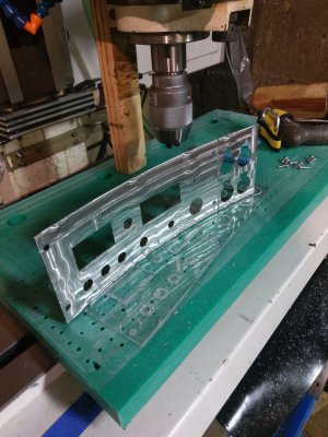
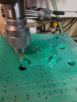
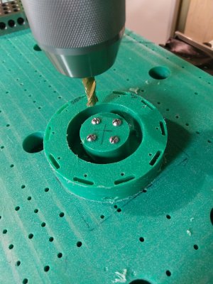
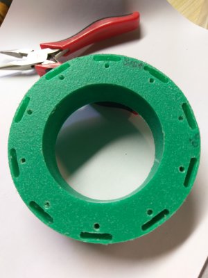
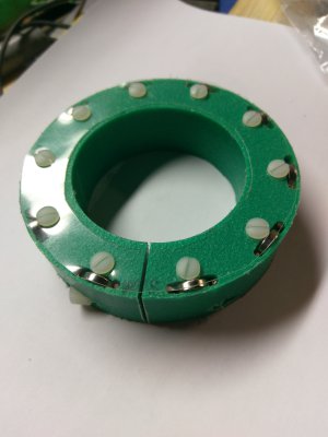
In this I showed a 10 magnet Hall Effect RMP sensor set up that I machined on a backer board that I made.
After I saw the slick way that
quickly aligns his vice I though I should post my backer board that I used to make the Hall Effect magnet mounts. To be able to always align my backer board to my Mill table and to align the work to the backer board .... I did some drilling!
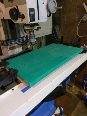
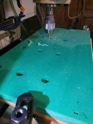
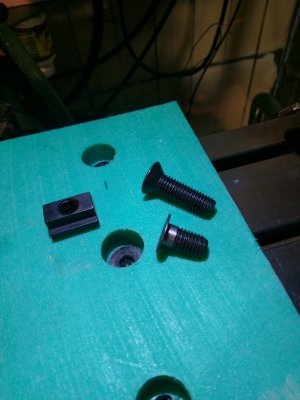
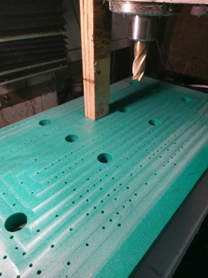
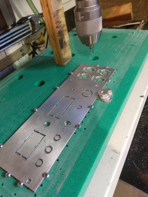
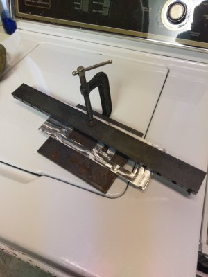
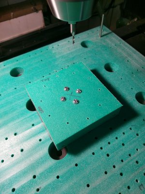
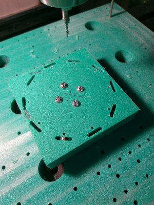
I measured the back edge of my table and found it was pretty good over the entire length ~22 inches, about 0.001" . Then I made a really nice backer board out of 1 inch thick nylon and aligned it to the back edge for a rough pass and clamped it down at the ends. I drilled tight ~ 3/16" holes in a line along the T-slots of the table and inserted drill rods in these holes. Then before bolting the backer board down again I pushed the drill rods through the backer board so that they were sticking into the T-slots and then push the board so that the the drill rods referenced off of the T-slot edges which were also measured to be straight. I machined several holes and counter sunk them for T-slot bolts to camp the board with these. I turned the T-Slot bolts head down to be very thin. So that the heads are only about 1/8 up from the table but clamping the backer board. The board has lots of thickness of material to waste before I would hit the T-slot bolts. I also drilled several hundred holes in this board on regular intervals using CNC code. The drill rods holes and drill rods align the board to the table with the many drilled holes are aligned to the drill rod holes by definition as well as the mill table. These hundreds of holes are then used to align my work. For thin materials I can also insert screws into the drilled holes after tapping and use the screw heads or heads with washers as clamps. I do not really need to have a 0.0005" alignment, but since the drilled holes are aligned to the length of table all is pretty good..... better than my clamping and far better than my Mill's current backlash.
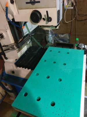
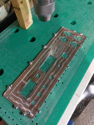
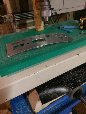
When completion the board can be removed and replaced quickly. Just insert the alignment pins, push them up to the T-slots for alignment, Clamp the board with the T-slot bolts, then the alignment pins can be removed if they are in the way. The work piece edge can either be aligned via the alignment pins or via pins that are put in the many drilled holes. In the last photo shows the board after I skim milled the surface to ensure that it was flat. (Forgive the wooden block that I use to ensure the mill head does not crash when the stepper is powered down.)
Attached are a some pictures of the backer board being made. I will post some photos of the first project I used the backer board for in the next posting.

Attached are a some pictures of the backer board being made. I will post some photos of the first project I used the backer board for in the next posting.
In this I showed a 10 magnet Hall Effect RMP sensor set up that I machined on a backer board that I made.
After I saw the slick way that
@Bill Kirkley
( https://www.hobby-machinist.com/threads/lining-up-machinist-vise.95601/ )quickly aligns his vice I though I should post my backer board that I used to make the Hall Effect magnet mounts. To be able to always align my backer board to my Mill table and to align the work to the backer board .... I did some drilling!
I measured the back edge of my table and found it was pretty good over the entire length ~22 inches, about 0.001" . Then I made a really nice backer board out of 1 inch thick nylon and aligned it to the back edge for a rough pass and clamped it down at the ends. I drilled tight ~ 3/16" holes in a line along the T-slots of the table and inserted drill rods in these holes. Then before bolting the backer board down again I pushed the drill rods through the backer board so that they were sticking into the T-slots and then push the board so that the the drill rods referenced off of the T-slot edges which were also measured to be straight. I machined several holes and counter sunk them for T-slot bolts to camp the board with these. I turned the T-Slot bolts head down to be very thin. So that the heads are only about 1/8 up from the table but clamping the backer board. The board has lots of thickness of material to waste before I would hit the T-slot bolts. I also drilled several hundred holes in this board on regular intervals using CNC code. The drill rods holes and drill rods align the board to the table with the many drilled holes are aligned to the drill rod holes by definition as well as the mill table. These hundreds of holes are then used to align my work. For thin materials I can also insert screws into the drilled holes after tapping and use the screw heads or heads with washers as clamps. I do not really need to have a 0.0005" alignment, but since the drilled holes are aligned to the length of table all is pretty good..... better than my clamping and far better than my Mill's current backlash.
When completion the board can be removed and replaced quickly. Just insert the alignment pins, push them up to the T-slots for alignment, Clamp the board with the T-slot bolts, then the alignment pins can be removed if they are in the way. The work piece edge can either be aligned via the alignment pins or via pins that are put in the many drilled holes. In the last photo shows the board after I skim milled the surface to ensure that it was flat. (Forgive the wooden block that I use to ensure the mill head does not crash when the stepper is powered down.)
Attached are a some pictures of the backer board being made. I will post some photos of the first project I used the backer board for in the next posting.
Attached are a some pictures of the backer board being made. I will post some photos of the first project I used the backer board for in the next posting.