Mills 1.3

Ghosty

Registered
Registered
Joined
Dec 14, 2016
Messages
53
Hi All,

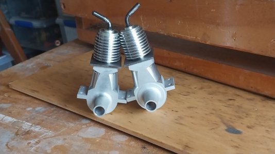
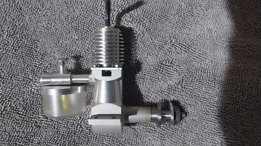
I looked into making a Mills 1.3 engine as they are getting very hard to get.

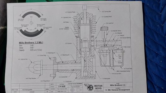
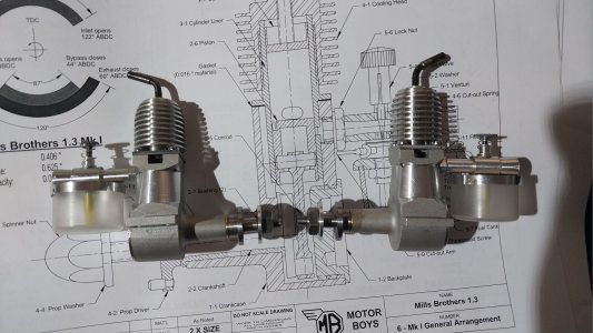
Found a web site with plans https://outerzone.co.uk/plan_details.asp?ID=13735

Printed the plans out and studied for a few hours. Have found many mistakes in downloaded plans in the past.

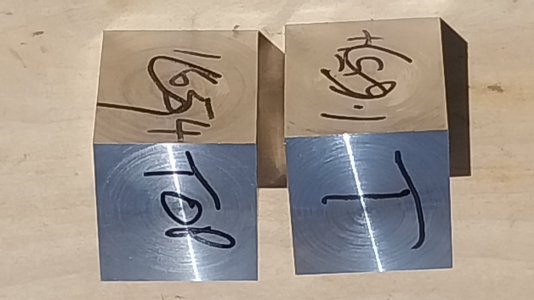
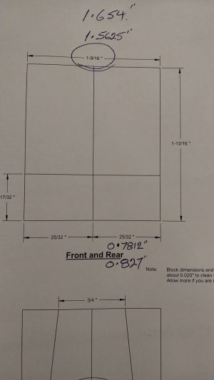
Found a mistake, width of the starter block for the crankcase was marked at 1-9/16" wide. on plans the width of the crankcase is total of 1.654" a difference of 0.0915".

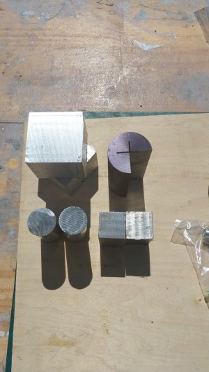
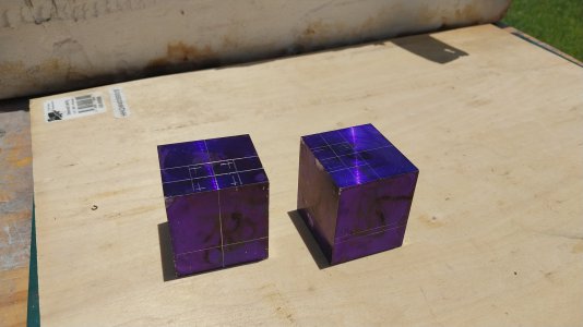
After double checking dimensions, I checked on what I had at hand. I had enough to get started with.

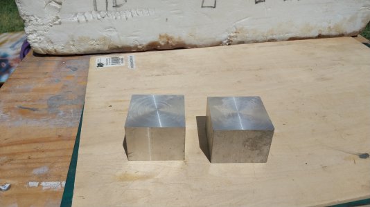
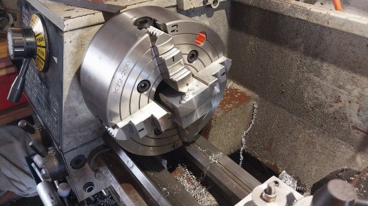
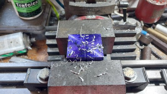
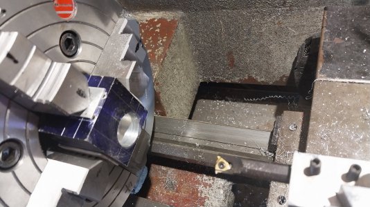
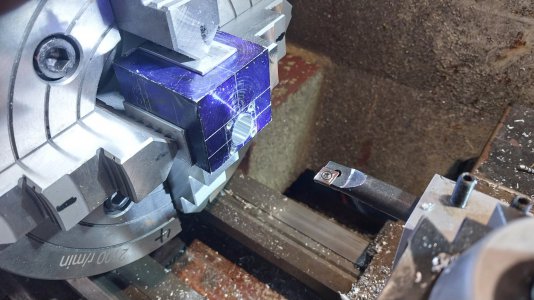
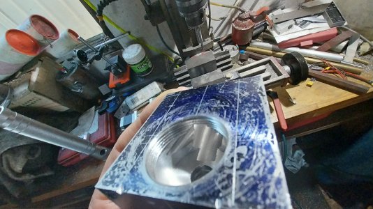
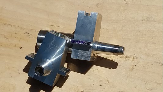
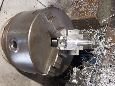
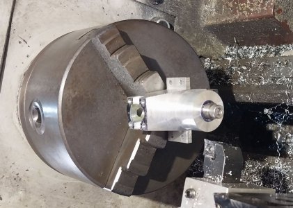
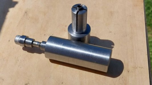
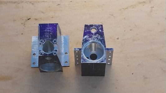
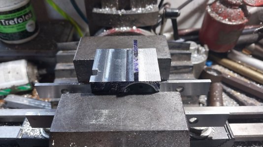
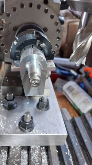
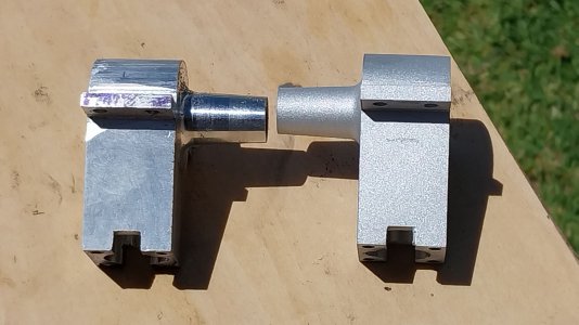
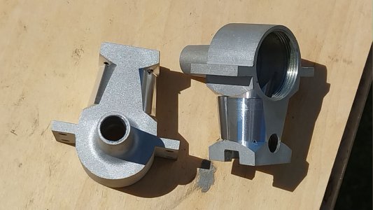
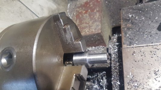
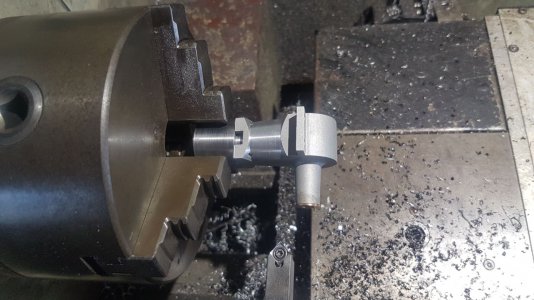
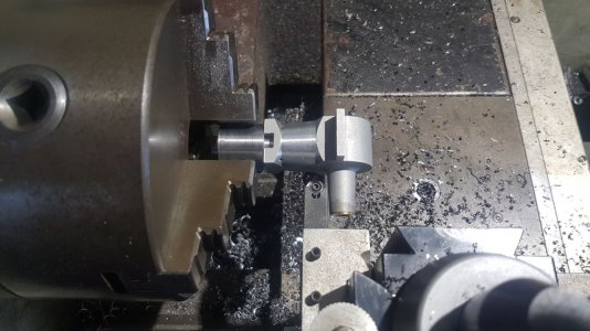
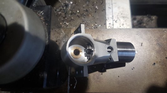
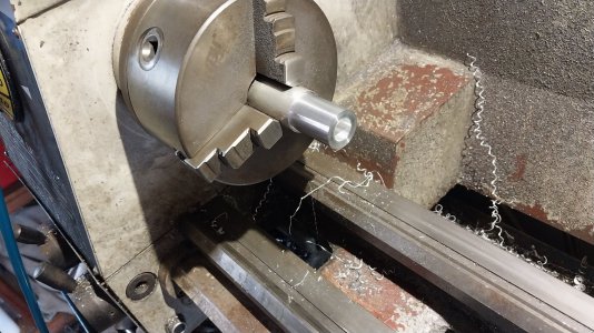
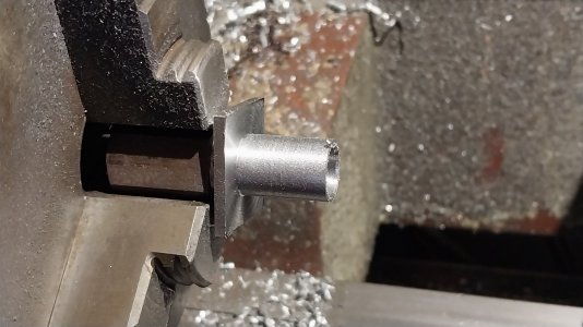
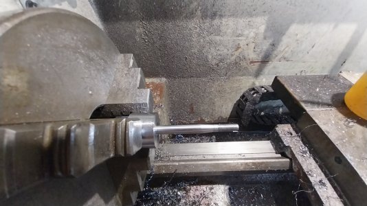
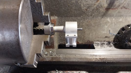
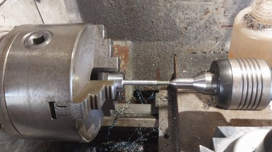
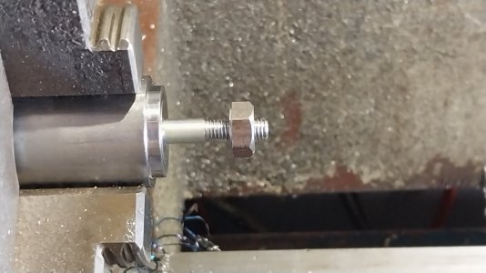
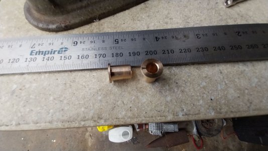
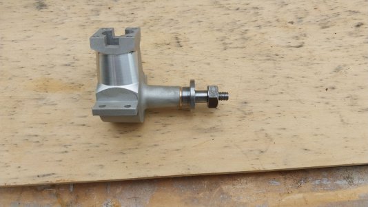
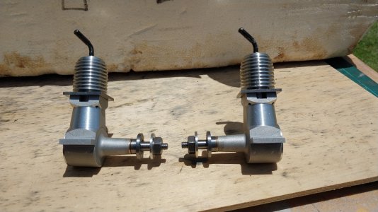
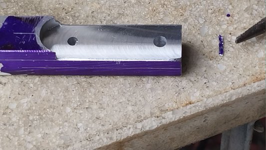
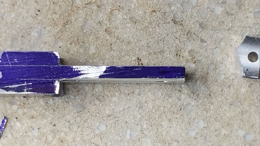
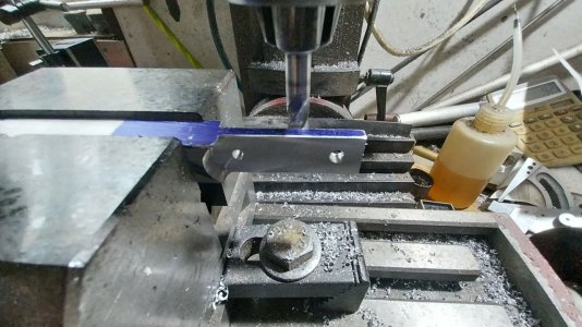
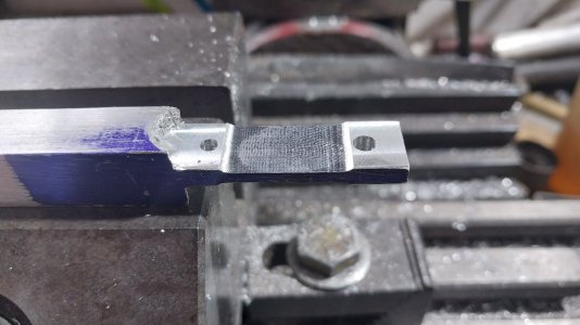
First got the material cut, then squared up and sized the block for crankcase.

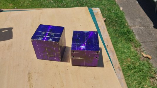
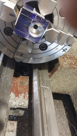
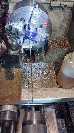
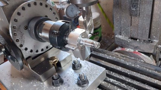
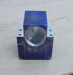
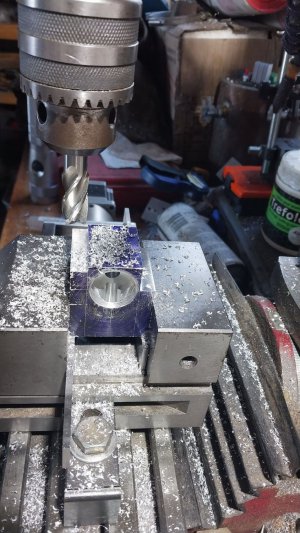
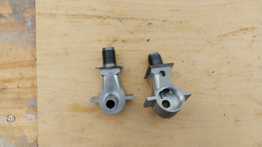
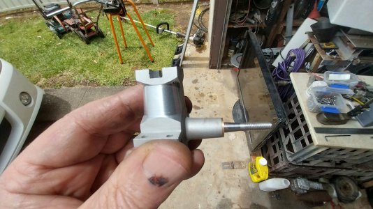
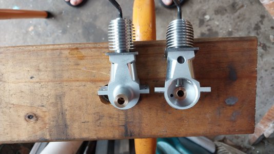
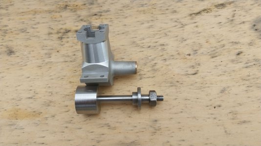
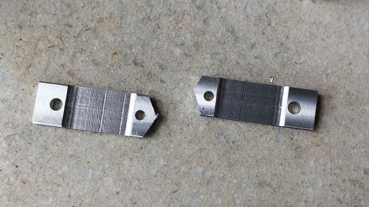
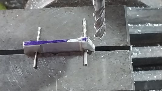
Then marked out and drilled 4 holes for the mounting lugs, then drilled and tapped the 4 holes for the cylinder mounting.

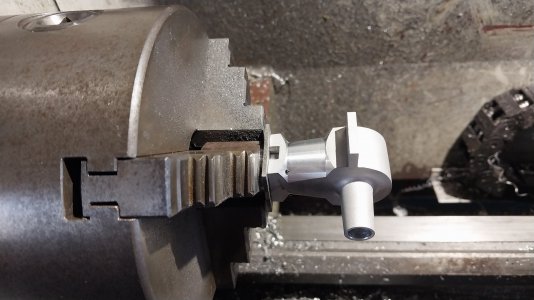
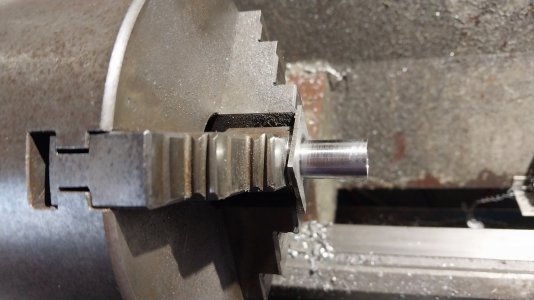
Will move on to crankcase machining tomorrow.

Cheers

Andrew
 

Attachments

  • 1.jpg
    1.jpg
    218.5 KB · Views: 9
  • 2.jpg
    2.jpg
    401.4 KB · Views: 9
  • 4.jpg
    4.jpg
    768.5 KB · Views: 9
  • 6.jpg
    6.jpg
    239.1 KB · Views: 9
  • 7.jpg
    7.jpg
    362.3 KB · Views: 8
  • 8.jpg
    8.jpg
    510.3 KB · Views: 9
  • 9.jpg
    9.jpg
    420.9 KB · Views: 17
  • 20230105_140933.jpg
    20230105_140933.jpg
    478.5 KB · Views: 16
  • 20230105_141802.jpg
    20230105_141802.jpg
    97.3 KB · Views: 15
Hi All,

Started the machining of the crankcase, setup, trued and centered, machined crankshaft pocket and bore, and threaded for backplate, thread is listed at 26TPI, as I can't cut imperial threads on my lathe, I used a 1mm pitch and the dia listed on the plans.

Then rotated the case, trued and centered then machined the cylinder bore.

Then moved to the mill, machined conrod relief, exhaust ports, and transfer port.

Will now move on to machining the outside or the case.

Cheers

Andrew
 

Attachments

  • 10.jpg
    10.jpg
    649.6 KB · Views: 14
  • 12.jpg
    12.jpg
    252.7 KB · Views: 14
  • 15.jpg
    15.jpg
    311.3 KB · Views: 12
  • 16.jpg
    16.jpg
    505.9 KB · Views: 12
  • 20.jpg
    20.jpg
    365.8 KB · Views: 12
  • 21.jpg
    21.jpg
    532.1 KB · Views: 13
Hi All,

Got on with the outside of the crankcase/body.

Started with the base/engine mount lugs, then the top sides, then cut the sides to the angle.

Then machined up two jigs to hold the case to machine on the lathe.

Machined the nose of the case and then on to the mill again to machine the base of the case.

Then glass bead blasting to get the finish on the case, then back on the lathe to do the final machining(sorry no pics of machining) of case.

Great care is needed when you do this step so you don'y drive the tool into the case.

Cheers

Andrew
 

Attachments

  • 31.jpg
    31.jpg
    308.8 KB · Views: 11
  • 30.jpg
    30.jpg
    213.9 KB · Views: 10
  • 29.jpg
    29.jpg
    252.4 KB · Views: 8
  • 28.jpg
    28.jpg
    157.4 KB · Views: 8
  • 35.jpg
    35.jpg
    72.3 KB · Views: 8
  • 27.jpg
    27.jpg
    183.4 KB · Views: 6
  • 26.jpg
    26.jpg
    228.5 KB · Views: 6
  • 24.jpg
    24.jpg
    305.9 KB · Views: 6
  • 23.jpg
    23.jpg
    60.7 KB · Views: 7
  • 22.jpg
    22.jpg
    303.1 KB · Views: 7
  • 32.jpg
    32.jpg
    171.1 KB · Views: 8
  • 33.jpg
    33.jpg
    209.5 KB · Views: 8
  • 34.jpg
    34.jpg
    208.4 KB · Views: 10
Hi All,

P.S. Remounted crankcase to show final cutting of case. tool post compound set at 7deg for cutting.

Access for grub screw is through the crankshaft pocket.


Cheers

Andrew
 

Attachments

  • 102.jpg
    102.jpg
    136.6 KB · Views: 10
  • 103.jpg
    103.jpg
    142.1 KB · Views: 9
  • 104.jpg
    104.jpg
    144.6 KB · Views: 8
  • 105.jpg
    105.jpg
    99.2 KB · Views: 9
  • 106.jpg
    106.jpg
    114 KB · Views: 10
Hi All,

Worked on the cylinder today.

Machined the first end out of square bar, thread should have been 0.540" x 26TPI, I used M14x1(0.551") as I cant cut imperial threads on my lathe.

Then, with a bit of 19mm hex bar, I drilled and tapped M14x1 to use as a jig to hold the cylinder , so I can machine the other end.

I machined down the other end to fit the case body, then drilled and reamed to 0.406".

Then I started on the cooling cap. Drilled and tapped M14x1, and checked fit of cylinder.

Machined the cooling fins, parted off, tapped for compression screw, then machined compression screw and assembled.

Cheers

Andrew
 

Attachments

  • 46.jpg
    46.jpg
    346.6 KB · Views: 9
  • 45.jpg
    45.jpg
    358.1 KB · Views: 9
  • 44.jpg
    44.jpg
    512.4 KB · Views: 7
  • 42.jpg
    42.jpg
    435.3 KB · Views: 6
  • 41.jpg
    41.jpg
    242.5 KB · Views: 7
  • 40.jpg
    40.jpg
    656.7 KB · Views: 7
  • 39.jpg
    39.jpg
    370.4 KB · Views: 7
  • 38.jpg
    38.jpg
    385.3 KB · Views: 7
  • 37.jpg
    37.jpg
    380.9 KB · Views: 6
  • 36.jpg
    36.jpg
    406.7 KB · Views: 8
Hi All,

Started on the crankshaft today, machined the crankshaft bearings from bronze and installed in cases, then reamed to size.

Machined and tapped the nut from 7/16" hex bar.

Centre drilled the crank blank, and then machined the end down for the threaded end as per plans.

Then machined crank down to suite the bearings, then machined taper on shaft.

Machined the prop drive hub, cut slots to drive hub instead of using drive pins as plans.

Cut groves with tool on side, 15thou deep.

Cheers

Andrew
 

Attachments

  • 56.jpg
    56.jpg
    305 KB · Views: 6
  • 55.jpg
    55.jpg
    549.4 KB · Views: 6
  • 54.jpg
    54.jpg
    465.4 KB · Views: 6
  • 51.jpg
    51.jpg
    364.5 KB · Views: 6
  • 50.jpg
    50.jpg
    575.4 KB · Views: 6
  • 49.jpg
    49.jpg
    312.9 KB · Views: 6
  • 48.jpg
    48.jpg
    527.3 KB · Views: 6
  • 47.jpg
    47.jpg
    364.6 KB · Views: 6
  • 57.jpg
    57.jpg
    324.4 KB · Views: 5
  • 58.jpg
    58.jpg
    443.9 KB · Views: 5
  • 60.jpg
    60.jpg
    437.2 KB · Views: 5
  • 61.jpg
    61.jpg
    457.7 KB · Views: 5
  • 67.jpg
    67.jpg
    477.9 KB · Views: 7
Hi All,

Started on the fuel tank/venturi today.

Machined the tank body from Perspex and alloy.

Machined needle valve from 1214, machined venturi/needle/jet in two pieces. Machined nut(5/16) from 10mm round bar.

Assembled needle/jet/ fuel tank top/venturi with loctite, when set drilled through and then cleaned out jet and needle threads.

Cut fuel tube piece and assembled fuel tank.

Cheers

Andrew
 

Attachments

  • 74.jpg
    74.jpg
    316 KB · Views: 5
  • 75.jpg
    75.jpg
    303.5 KB · Views: 5
  • 74.jpg
    74.jpg
    316 KB · Views: 5
  • 75.jpg
    75.jpg
    303.5 KB · Views: 5
  • 76.jpg
    76.jpg
    120.6 KB · Views: 5
  • 77.jpg
    77.jpg
    158.8 KB · Views: 5
  • 78.jpg
    78.jpg
    241.6 KB · Views: 5
  • 79.jpg
    79.jpg
    223.1 KB · Views: 7
  • 80.jpg
    80.jpg
    542.5 KB · Views: 8
  • 83.jpg
    83.jpg
    287.9 KB · Views: 8
Hi All,

Started with conrod machining today.

Used a piece of 7075 10mm alloy plate, cut a 10mm slice off and squared up.

Marked out and drilled and reamed big and little ends to size.

Then machined to thickness, then machined centre section to thickness.

With the use of a 1mm(big end) and a 1.5mm(little end) drill bits I machined the outer sides to size.

Then machined the outer big, and little ends.

Still have the final finishing to do.

Cheers

Andrew
 

Attachments

  • 85.jpg
    85.jpg
    262.8 KB · Views: 3
  • 86.jpg
    86.jpg
    316.8 KB · Views: 3
  • 87.jpg
    87.jpg
    162.7 KB · Views: 3
  • 88.jpg
    88.jpg
    220.5 KB · Views: 3
  • 89.jpg
    89.jpg
    438.7 KB · Views: 3
  • 90.jpg
    90.jpg
    200.3 KB · Views: 3
Back
Top