- Joined
- May 2, 2014
- Messages
- 217
I just completed several upgrades to my LMS 3960 Hi-Torque Solid Column Mini-Mill that were relatively simple to do, yet the end result adds greatly to the capability of this fine little machine. I will describe the changes with photos and supplier info at the end of this post.
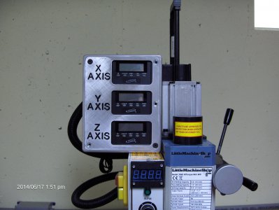
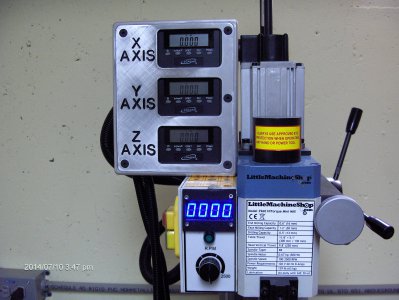
The first change was to add a digital tachometer. I had looked at the tach offered by LMS that plugs in to an existing port but it was a bit more than I wanted to spend at the time. I found a supplier on-line that makes a kit which requires a little work to make a faceplate and lens, but at a lesser cost. They offer a direct plug in option or a kit that connects inside the control box. That is the unit I bought to eliminate a wire hanging off the machine. I made a faceplate and lens that mount directly on the control box rather than fabricate a separate enclosure. It looks very good. The tach can be wired to replace the fault lamp and display FAULT on the readout. It also can eliminate the power on lamp because the display lights up when the power is on.
The next upgrade was installation of the LMS airspring to support the headstock rather than the torsion lever on the side of the column. It also increases the available travel of the headstock a bit. The kit instructions are very good.
I had previously purchased the LMS kit to convert the axis screws and dials from .062 to .050 per rev. This conversion requires disassembly of the table and cross-slide but isn’t that difficult if you follow the excellent instructions furnished with the kit. I had put the installation off for a while since I wasn’t in a hurry to get into it.
I wanted DRO’s on my machine and I found that info on this forum. I purchased three igaging units from David, a 6 inch scale and two 12 inch scales, all with remote readouts.
Once they arrived, I was very pleased with them. The instructions were minimal but it didn’t take much ingenuity to figure them out. None of the mounting brackets were suitable for my application but making appropriate mounts wasn’t too difficult.
I want to say that I had read reports here about how easy they were to install in a short period of time. I had also read reports on other sites that they weren’t reliable or very accurate and prone to failure. I believe that many of the complaints were due to hasty installation and poor alignment.
I took great pains to align my units carefully. It is important (to me) that the scale must not lift or be distorted anywhere in the travel. The Y and Z axis units are installed with the scale mounted to the frame and the reader mounted on the sliding member. The X axis unit has the scale mounted on the sliding member and the reader mounted on the cross slide.
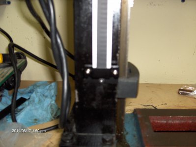
The Z axis (headstock) was the easiest to install on the left side because the mounting surface and the sliding surface were machined flat and adjacent in the same plane. This was a clean installation since the torsion lever and the original travel scale and pointer had been removed during installation of the airspring. A 3/16” plastic mounting pad on the headstock for the reader allowed the scale mounting feet to be screwed directly to the column without shimming. Alignment was checked by leaving the scale screws a bit loose and moving the headstock up and down the full length of travel. If the scale doesn’t lift or twist, then the alignment is dead on. The 12 inch unit was used as is, even though the head doesn’t have that much stroke.
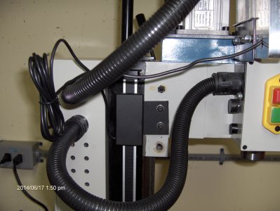
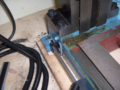
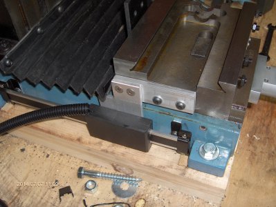
The Y axis was a bit of a challenge. I needed to mount the 6 inch scale on the base of the machine on the left side. I originally mounted it with the scale mounting feet resting on the hold down ears on the mill base but the mounting bolts for the machine would not be able to be tightened or loosened without removing the scale. During the installation of the various items of these retrofits, I had to unbolt the machine and swivel it to allow drilling and tapping for brackets. I decided that another approach was necessary, so I plugged the holes I had tapped with set screws.
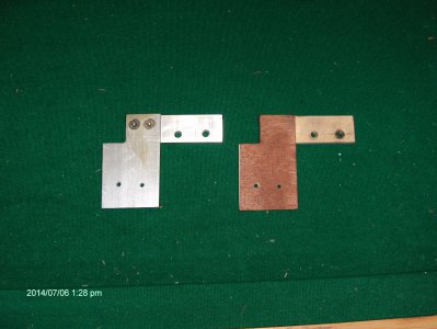
It seemed a better idea to mount the scale between the mounting lugs of the machine. One problem was that regardless of where the scale was mounted, the machine base had a draft angle due to casting which would make the scale lean in at the top. I determined that the draft angle was 2°. I am a model airplane enthusiast and know that 2° engine offset is commonly used in profile models. I know a company that makes modeling components and they offer 2° aluminum shims that were perfect for this application. I ordered a pair and after drilling a couple of holes in each one, they were going to be perfect.
A potential snag was I had to shorten the 6 inch scale to fit in between the mounting lugs of the machine. Some quick measurements indicated that if the scale was shortened so that the feet would fit, I wouldn’t have enough travel available to cover the full stroke of the Y axis. I reversed the mounting brackets on the scale to put the L on the inside. Trimming the scale about half an inch allowed everything to fit with enough travel. This meant the scale feet had to be mounted first and then the scale put in place and the hold downs screwed down. Not really a problem.
Alignment was once more considered. The machine is mounted on a couple of boards glued and screwed together and screwed to the bench. Through bolts hold the machine in place. To make sure the mounting brackets on the scale were located properly, I glued small pieces of a Popsicle stick on the mounting board, right under the scale feet for them to rest on. Drilling and tapping the 10-32 screw holes in the base was a snap (as it was on the headstock scale installation) and the scale was mounted plumb and straight and parallel to the Y axis slide.
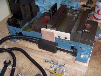
Mounting the reader was a bit of a challenge because the majority of the slide stroke was to the right of the scale. This required mounting the reader on an offset bracket. That would allow full travel of the Y axis without bottoming the reader out on either end. It was close, but doable.
Alignment was once more a challenge. The reader had to mount 7/16 off the surface of the cross slide. A lot was cut and try. I found that making the bracket out of two pieces of model aircraft plywood, 3/16 and 1/4 glued together proved to be a suitable test mount to make sure everything was aligned and slid without binding. Stepping back a bit, I had already removed the table and feed screws, so I was able to move the cross slide back and forth by hand, checking alignment and operation. Once this checked out, I made a permanent bracket out of aluminum to replace the plywood.
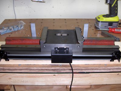
The X axis was the last to do. I had the table off the machine to change the feed screw. I set it face down on the bench on a nice flat board. The scale was mounted with the edges of the mounting feet touching the board. This put the scale parallel to the top surface of the table.
The reader was mounted on the cross slide on a 3/16 plastic pad that had to be shimmed out to clear the back of the table, since the mounting surface on the cross slide was just behind the edge of the table. That meant the mounting feet of the scale could not sit flat on the table. Shimming with washers was a solution. I found after many trips to the hardware store that #10 washers vary in thickness. Stainless steel washers are the best @ .030. Regular stamped washers can vary from .044 to .060. Plastic washers measure .064. Mixing and matching can usually give what you need. The X axis scale and reader are working well but I intend to redesign the mount to eliminate the washer shims and put the scale feet flat on the table. With the machine back together, I have the capability to mill exactly what I need for steps and/or offsets on a mounting pad.
The conversion of the feed screws and nuts was easy following the instructions provided, so I won’t go into it.
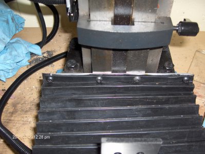
Another upgrade was the rear way cover. It seems that the machines with the tilt head come with a rear bellows but the solid column machines don’t. I quick email to LMS and I had a rear bellows to install. The tapped holes in the cross slide were already there but I needed to drill and tap the column for 6mm screws. The bellows was an easy fit but I didn’t care for the thin metal strip provided that holds the bellows in place, since the ends were unsupported. An easy fix was a strip of aluminum as a backer and a couple more screws to hold the ends together.
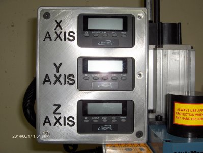
Finally, I need to mention the nice readout mounting bracket that I discovered. Someone here had bought a bracket for 2 axes. I did some research and found the manufacturer. I asked if they could make one for all three axes and they said yes. I placed an order and had it in a couple of weeks. The quality is excellent. It mounts to the small sheet steel bracket that was already on the machine, used to mount the LMS tach which is magnetic. I bought some convoluted split plastic sheathing to cover the wires for protection.
One last conversion that was dirt cheap and easy was the replacement of the double nuts used on the feed screw shafts by using elastic stop nuts. Adjusting the double nuts is always a problem because of the dish shape of the handwheels. Trying to lock one nut against the other usually ends up with too much play or binding up. The elastic stop nut is screwed on until you get just the right feel. Done deal for $.080 each at the hardware store for 8mm.
One tip I have about drilling and tapping. I used Big Gator drilling and tapping guides. I have all four covering drilling and tapping US standard and metric holes and threads. They can reduce breakage of small taps and give good results for drilling and tapping straight holes on both flat and round surfaces.
Lastly, the problem of cleaning the chips out of small holes after drilling or tapping is a problem if you don’t have a compressor handy. I found a can of compressed air which is used to clean computers to be very effective. Place the end of the plastic tube in the hole and give the can a squirt. Just the right amount of pressure and you have a clean hole.
Air spring kit, feed screw and dial kit, bellows kit.
info@littlemachineshop.com
Billet DRO readout holder
konkel521@yahoo.com
Igaging DRO’s
tooldoc@cheqnet.net
Tach Kit
nelsonjm@macpod.net
Tapered shims
jlee9@cox.net



Last edited:

