- Joined
- Sep 22, 2010
- Messages
- 7,223
Description
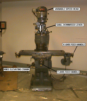
Milling machines are very versatile. They are usually used to machine flat surfaces, but can also produce irregular surfaces. They can also be used to drill, bore, cut gears, and produce slots. The type of milling machine most commonly found in student shops is a vertical spindle machine with a swiveling head. Although there are several other types of milling machines, this document will focus only on the vertical milling machine.
A milling machine removes metal by rotating a multi-toothed cutter that is fed into the moving workpiece. The spindle can be fed up and down with a quill feed lever on the head.
(click here for video) 656kB.
The bed can also by fed in the x, y, and z axes manually. In this clip the z axis is adjusted first, then the y, than the x.
(click here for video) 1.33MB
Once an axis is located at a desired position and will no longer be fed, it should be locked into position with the gibb locks.
(click here for video) 247kB
Most milling machines are equipped with power feed for one or more axes. Power feed is smoother than manual feed and, therefore, can produce a better surface finish. Power feed also reduces operator fatigue on long cuts. On some machines, the power feed is controlled by a forward reverse lever and a speed control knob.
(click here for video) 739kB
Tramming the Head
The head of a vertical milling machine can be tilted from side to side and from front to back. This allows for versatility of the machine, but these adjustments can drift. Occaisionally, one should check and adjust the head so that the spindle will be normal to the plane of the table. Install a dial indicator into the spindle so that the dial is offset at least six inches from the axis of the spindle and the indicator probe is facing down. Lower the spindle until the dial indicator contacts the table then registers about one half of a revolution. Set the dial indicator is toward you and set the bezel to zero. Rotate the spindle by hand 180 degrees. If the dial indicator still reads zero, the spindle is aligned front to back. If not, adjust the head until the dial reads half of the original reading and iterate the entire process until the error falls within acceptable limits. Repeat the process with the dial displaced left and right to alight the head side to side.
Squaring the Vise
Work on a milling machine is most often held in a vise clamped onto the bed. To make features aligned with the edges of the stock, it's neccessary to align the vise with the feed axes of the mill. To do this, mount the vise on the bed and secure it with T-bolts, but only lightly so as to permit adjustment of the orientation of the vise. Mount a dial indicator in the spindle of the machine with the probe facing away from you. Lower the spindle and run the bed of the table back until the fixed jaw of the vise is in contact with the indicator and further until the indicator registers one half of a revolution. Set the bezel to zero. Use the cross feed to run the indicator ocross the face of the vise. If the vise is squared, the indictor will remain at zero. If the dial indicator does not read zero, tap lightly with a soft hammer to realign the vise reduce the indicator reading to half of its previous value. Iterate this procedure until the dial indicator reads zero through the full travel across the face of the vise. Tighten down the T-bolts be careful not to change the vise orientation. Recheck the alignment of the vise.
Types of Milling Cutters
In vertical mills, milling cutters with solid shafts are usually used. Milling cutters with keyed holes are predominantly for use in horizontal mills. End mills are designed for cutting slots, keyways and pockets. Two fluted end mills can be used to plunge into work like a drill. End mills with more than two flutes should not be plunged into the work. Ball end mills can produce a fillet. Formed milling cutters can be used to produce a variety of features including round edges.
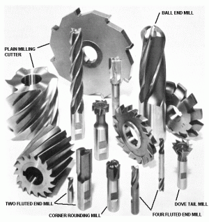
An Assortment of Milling Cutters
Removing and Installing Milling Cutters
To remove a tool, move the quill to the highest position and lock it in place. Then, engage the brake while loosening the draw bar with a wrench. Ensure that the draw bar's threads are still engaged in the collet. Tap on the end of the draw bar to release the collet from the spindle. If the threads of the draw bar are not engaged, the milling cutter will fall, and could be damaged. Finally, unscrew the drawbar from the collet.
(click here for video) 2.29MB
To install a tool, place the desired milling cutter in a collet that fits the shank of the cutter. Insert the collet into the spindle. Ensure that the key way on the collet mates properly with the key in the spindle. While holding the tool with one hand, start the threads of the draw bar into the collet by hand. Use a wrench to tighten the drawbar down with one hand while holding the brake.
Climb vs. Conventional Milling
When milling, one should be aware of the difference between conventional,and climb milling. In conventional milling, the workpiece is fed into the rotation of the cutter. This type of cut requires lower forces and is preferred for roughing cuts. In climb milling, the work moves with the rotation of the cutter. This produces a better finish. It is not recommended if the workpiece cannot be held securely or cannot support high forces.
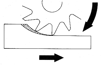
Conventional Milling
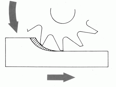
Climb MIlling
Calculating Speeds and Feeds
Cutting speed refers to the speed at which the tool point of the cutter moves with respect to the work measured in feet per minute. Feed is the rate at which the work moves into the cutter measured in feed per tooth revolution. Feeds and speeds affect the time to finish a cut, tool life, finish of the machined surface and power required of the machine.
The cutting speed is mostly determined by the material to be cut and the material of the tool. To find the right speed for any task, refer to the Machinery's Handbook or other reference. To calculate the proper spindle speed, divide the desired cutting speed by the circumference of the tool expressed in feet. The feed rate depends on the width and depth of cut, finish desired and many other variables. To calculate the desired feed setting from the feed rate, multiply feed per tooth per revolution by number of teeth and rpm of the spindle.
Setting Spindle Speed
Spindle speed is varied by changing the geometry of the drive train. On many modern machines, it can be adjusted continously with a hand crank. The spindle must be turning to make the adjustment. A dial indicator reads the speed in rpm.
(click here for video) 738kB.
The spindle speed dial indicator shown above has two scales, one for low range, and one for high range. The machine is swithched between ranges with a lever. Sometimes, the spindle must be rotated slightly to allow the gears to mate properly.
(click here for video) 370kB.
Using an Edge Finder
Before doing precise work on a milling machine, one must locate the edges of a part accurately. An edgefinder is designed to help you do this. An edgefinder is composed of two concentric cylinders, spring loaded together. To use it, offset the two halves slightly so that there is a wobble as it spins. Then, move the part into the tool slowly. The edge finder will center up, then break out of concentricity suddenly. At that point, reset the dial indicator or digital readout for that axis of the machine to a value equal the radius of the edgefinder. Repeat the process at least once.
(click here for video) 2.46MB
Using the Micrometer Dials
Most milling machine manual feeds are equipped with dial indicators. If you know how far you want to feed the bed, you can set the dial indicator to that number (in thousandths of an inch). Just turn the locking ring counterclockwise to free the dial indicator, set the dial, and lock in the setting. Be cetain that the backlash in the mechanism driving the table is taken up prior to setting the dial indicator.
(click here for video) 1.19MB
Many modern machines have digital readouts. These are preferred since they measure the bed position directly so you need not be concerned with backlash. They also readout bed position in metric units if desired.
Squaring Stock
To create a square corner on a part, first orient an already finished edge vertically in the vise and clamp lightly onto the part. Set a machinist's square against the finished edge and the bottom of the vise. Lightly tap the part with a plastic hammer to align it with the square. Clamp the vise down securely. Now the top edge of the part is ready to be milled to horizontal.
(click here for video) 1.23MB
Face Milling
It is often necessary to create a flat face on a large part. This can be done best with a facing cutter. Select a cutter about one inch wider than the workpiece so that the facing can be accomplished in one pass.
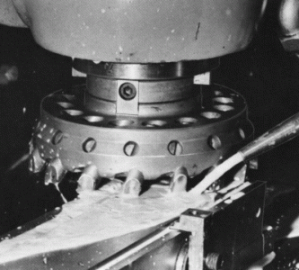
Face Milling
Milling Slots
End mills are designed to cut square slots. They will produce a slot to within two onethousandths of an inch in one pass. If greater accuracy is required, use an end mill a little smaller than the desired slot. Measure the slot produced and open it to the desired dimension with a second pass. The following clip shows and end mill cutting a slot. Note that the depth of cut is approximately equal to the diameter of the cutter.
(click here for video) 1.31MB
Advanced Work Holding
To hold round stock more securely in a vise, use a v-block. The work can be held vertically or horizontally.
(click here for video) 1.11MB
Round stock often cannot be held securely in the vise without damaging the work. A collet block is designed to hold round stock. Square collet blocks allow the part to be indexed to put in features at 90 degree increments. To mill features at 60 degree increments, use a hexagonal block.
(click here for video) 3.19MB
A workpiece can be set up easily when the desired features are parallel with or perpendicular to the workpiece edges. When the features are at an angle to the edges, more ingeniuty is required. Here, an angle plate is used to set the position of a vise within a vise. Thus a slot can be milled into a workpiece at any desired angle.
(click here for video) 418kB
Some parts don't fit well into a vise. These parts can be secured directly to the bed of the machine with hold down clamps. It is good practice to create a gap between the bed and the work with parallels. The clamps should be tilted down slightly into the work.
(click here for video) 1.95MB
To create circular features on a mill, a rotary table can be installed onto the bed. The table allows the workpiece to be rotated. A dial indicator allows precise control of the angle of rotation.
(click here for video) 290kB

