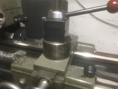
Modding the compound screw nut for backlash.

LX Kid

H-M Supporter - Gold Member
H-M Supporter Gold Member
Joined
May 26, 2015
Messages
773
"What if"using two brass nuts instead of one! I do realize the screw cover will have to be made new to facilitate another nut at the same level as currently exists. Don't know if I can put in words what my idea is so I'll make a sketch in awhile. The screw cover has a step down so is why a new cover will have to be fabricated. A stiff spring between the two nuts would load an opposing force to adjust backlash. I just figure there has to be a workaround for this backlash. Mine is not as major as some being about .006" backlash. My brass nut is new but I have ordered another nut to play around with. If anyone has suggestions besides "forget it" let me know about my folly or how you think this mod might be achieved.
 
I think you’re showing a lathe, not a mill. My lathe uses two nuts turned against each other, no spring. Remember that a spring is going to be the working stop in one direction, either outside facing or while boring. I could see that leading to some difficultly chasing dimensions and possibly chatter problems for whichever direction applies.
 
I did just that on my Atlas/Craftsman 6 x 18 cross slide. I used an old cross slide nut as the second nut with a compression spring between the two nut to provide a bias. The second nut is mounted to the back of the main nut and the cross slide cover was modified with a slot to fit the mounting boss on the nut to allow lateral movement but to prevent rotation of the nut. The modification dropped backlash to .002" on a well worn lead screw. The floating arrangement of the second nut allows correction for varying wear of the lead screw over the full range of travel.

Mounting the floating nut on the back side insures positive inward feed of the cross slide. There could be a problem when boring as the spring tension would be supplying the cutting force. A stronger spring will minimize this but will also increase wear. Alternatively, you can bore from the back side by inverting the boring bar.
 
FWIW, A spring would work across. variable backlash as typically the leadscrew is worn more over a small area.
 
I think you’re showing a lathe, not a mill. My lathe uses two nuts turned against each other, no spring. Remember that a spring is going to be the working stop in one direction, either outside facing or while boring. I could see that leading to some difficultly chasing dimensions and possibly chatter problems for whichever direction applies.
FWIW, A spring would work across. variable backlash as typically the leadscrew is worn more over a small area.

Use of the spring allows for varying wear on the lead screw. Old dogs like my 6 x 18 have a well worn center section on the lead screw with nearly virgin regions at either end. If wear isn't too great, a split nut with a method of bias between the two halves is a better option. My G0602 used a pointed set screw to create the bias by wedging between the two halves. Others use a screw to pull the two halves together.
 
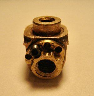
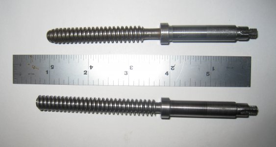
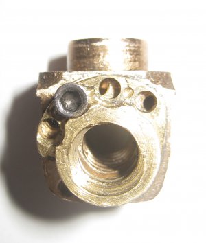
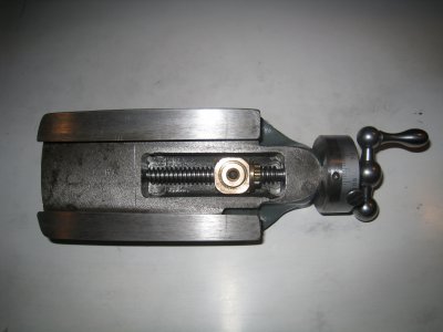
If you will pardon me your photos show the cross slide, but the same thing applies. I have experimented with spring loaded take-up nuts and found that a strong enough spring only results in a lot of added friction. I found the best result is to use an adjustable "jam nut" against the existing nut. If the screw is not worn in the middle you can get backlash down to a couple of thou, if not adjust it at the least worn part of the screw so you don't have tight spots. I did this on both the cross slide and the compound. I've included photos of the compound fix on my 10" SB. Very tight space so the jam flange and adjusting holes were made after I knew where the nut would sit. Jam nut can be moved by half a hole. Also made a slightly longer screw for a little extra travel.
Hope this helps.
 

Attachments

  • IMG_6310.jpeg
    IMG_6310.jpeg
    1.1 MB · Views: 15
  • IMG_6324.jpeg
    IMG_6324.jpeg
    858 KB · Views: 14
  • IMG_6334.jpeg
    IMG_6334.jpeg
    402.8 KB · Views: 14
  • IMG_6337.jpeg
    IMG_6337.jpeg
    1.9 MB · Views: 14
If you will pardon me your photos show the cross slide, but the same thing applies. I have experimented with spring loaded take-up nuts and found that a strong enough spring only results in a lot of added friction. I found the best result is to use an adjustable "jam nut" against the existing nut. If the screw is not worn in the middle you can get backlash down to a couple of thou, if not adjust it at the least worn part of the screw so you don't have tight spots. I did this on both the cross slide and the compound. I've included photos of the compound fix on my 10" SB. Very tight space so the jam flange and adjusting holes were made after I knew where the nut would sit. Jam nut can be moved by half a hole. Also made a slightly longer screw for a little extra travel.
Hope this helps.
Yup! Your correct about pics are of the cross slide. Not the first time I've screwed up with the pics. I can live with the cross slide backlash and is the compound that I'm concerned about. Seems like they might make some kind of industrial epoxy for coating of the inside worn threads. An adhesive that's not specifically for my application but who knows "maybe." Don't get old cause you get goofy wrong ideas all the time! Ha Ha

In my 6" lathe there is not a lot of room for a jam nut. I'm going to have to relook at my whole approach to the backlash problem with the "COMPOUND SLIDE" delima! Thank for your suggestion and help.
 
I just finished removing my "compound slide" and I just don't think a second nut is going to work due to the smallness of the slide. There just doesn't seem to be any room. The housing is not build the same way as the SB 10" as pictured above. Maybe try and put a "slight" squeeze, with a vice, on the sides to see how that would work.
 
I did just that on my Atlas/Craftsman 6 x 18 cross slide. I used an old cross slide nut as the second nut with a compression spring between the two nut to provide a bias. The second nut is mounted to the back of the main nut and the cross slide cover was modified with a slot to fit the mounting boss on the nut to allow lateral movement but to prevent rotation of the nut. The modification dropped backlash to .002" on a well worn lead screw. The floating arrangement of the second nut allows correction for varying wear of the lead screw over the full range of travel.

Mounting the floating nut on the back side insures positive inward feed of the cross slide. There could be a problem when boring as the spring tension would be supplying the cutting force. A stronger spring will minimize this but will also increase wear. Alternatively, you can bore from the back side by inverting the boring bar.
During my little adventure making a (initially) near zero backlash nut for the compound slide out of bronze-loaded JB-Weld, I did think about a scheme used on old Citroen front wheels which used a helix thing to take up brake pad wear. The mechanical arrangement had a multi-start helix thing to adjust a cable operated handbrake that moved the start point for the hydraulic disc brake pistons. (I know - a handbrake on the front driving wheels!! ). I thought something like that could be applied to anti-backlash nuts.

Where you have the slide driven in one direction by the screw, and in the other direction across the backlash by spring pressure, you still have "backlash", albeit somewhat stiffer version. Having a 2-part compound nut, with one end adjusted up as explained by @Canuck75 is exactly right, though it does require fairly constant re-setting.

My scheme imagined a axial spring to spin the "other nut" up against the lead screw thread to take out the backlash, incrementally creeping it around as the nut wears. It might have worked, but there was just not enough space in that little compound. Also - I fell prey to Stefan Gotteswinter and Robin Renzetti. I will be going for the solid toolpost mount, just as soon as I can score a big enough chunk of iron. :)
 
If you have backlash problems in the compound and you only occasionally use it, one option is to replace it with
a solid "plinth" or block of steel and only use the compound when you need it. A number of forum members have
done this to their lathes and are happy with the increased rigidity. They're nice to work around as well: no chance
of accidentally bumping into the handle on the compound just before your last pass... :)

Like this:


IMG_1631.jpeg
 
Back
Top